Intraluminal flexible stent device

a flexible, intraluminal technology, applied in the field of intraluminal stents, can solve the problems of increased strain, increased potential for permanent deformation of the stent segment in the immediate area, and inside bends that interfere with each other or overlap, and achieve the effect of greater flexibility of the sten

Inactive Publication Date: 2011-11-08
MEDTRONIC VASCULAR INC
View PDF7 Cites 36 Cited by
  • Summary
  • Abstract
  • Description
  • Claims
  • Application Information

AI Technical Summary

Benefits of technology

[0010]The present invention is directed to an intraluminal stent device that solves many of the problems that occur when a stent is tracked through a potentially winding body conduit such as a blood vessel. In particular, stent bands of the present invention use a combination of short, mid-sized, and long segments to form a series of consecutive tapered gaps between unconnected closed-ended turns of adjacent bands when adjacent bands are connected together to form the stent body. The series of consecutive tapered gaps provide greater flexibility for the stent when the stent is tracked around a small radius bend in a vessel.
[0011]In one embodiment, the stent has generally undulating bands connected together. Each band has a pattern of undulations formed from long, short and mid-sized segments connected together by turns. The segments and turns form peaks and valleys of the stent, by which adjacent bands may be connected. In one particular embodiment, the pattern includes a repeating series of five segments and five turns which connect the segments together. The repeating series includes a long segment and a first short segment coupled by a first turn. The first short segment is coupled to a first mid-sized segment by a second turn. The first mid-sized segment is coupled to a second mid-sized segment by a third turn. The second mid-sized segment is coupled to a second short segment by a fourth turn, and the second short segment is coupled to the next series by a fifth turn. The order of the five segments has a LSMMS configuration (long, short, mid-sized, mid-sized, short). When adjacent bands are connected together to form the stent body, the LSMMS series having various segment lengths form a series of consecutive tapered gaps which provide greater flexibility for the stent. For example, the series of consecutive tapered gaps between the unconnected closed-ended turns of adjacent bands allow the stent to flex with little or no interference with adjacent bands when the stent is tracked around a small radius bend in a vessel.
[0012]The consecutive tapered nature of the series of gaps is advantageous in that the larger gaps optimally occur between turns of adjacent bands which generally experience the greatest amount of interference when the stent is tracked around a small radius bend in a vessel. Further, the smaller gaps also add to the stent body's flexibility while simultaneously providing greater scaffolding than that provided by the larger gaps. Greater scaffolding means that more area of the vessel walls is being supported directly by parts of the stent.
[0013]Another important aspect of the present invention includes minimizing the length of the longest rigid element of the stent to further improve flexibility. The longest rigid element of a stent body occurs at the location of a connection between adjacent bands. The lengths of the segments on both sides of the connection essentially form a rigid element which must be tracked around the bends of a vessel. By minimizing the length of this rigid element, the length which must be tracked around the bends of a vessel is shortened and thus the stent is easier to advance.

Problems solved by technology

Often, the turns of adjacent bands on the inside of the vessel bend will interfere with each other or overlap.
Such overlapping creates greater strains and an increased potential for permanent deformation of the stent segments in that immediate area.

Method used


Image

  • Intraluminal flexible stent device
  • Intraluminal flexible stent device
  • Intraluminal flexible stent device

Examples


Embodiment Construction

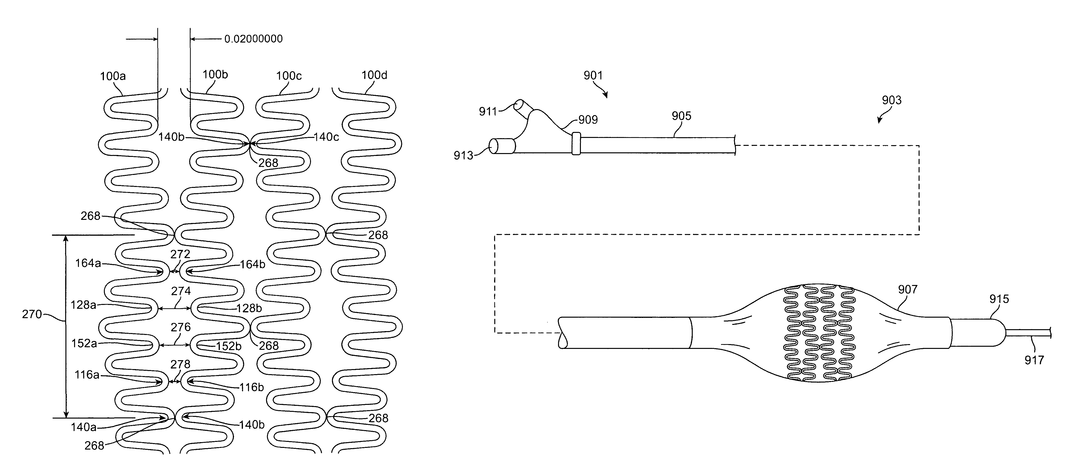
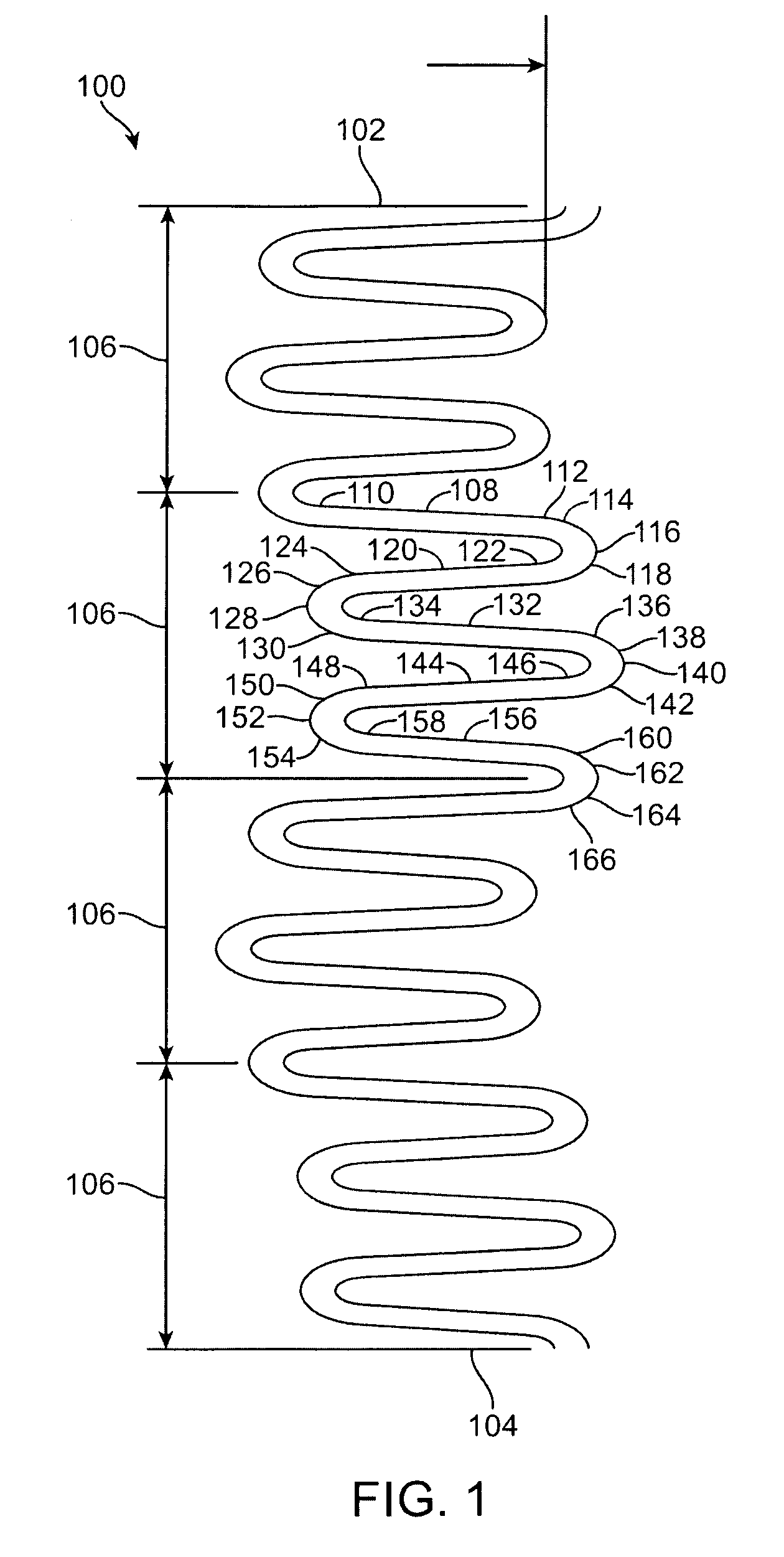
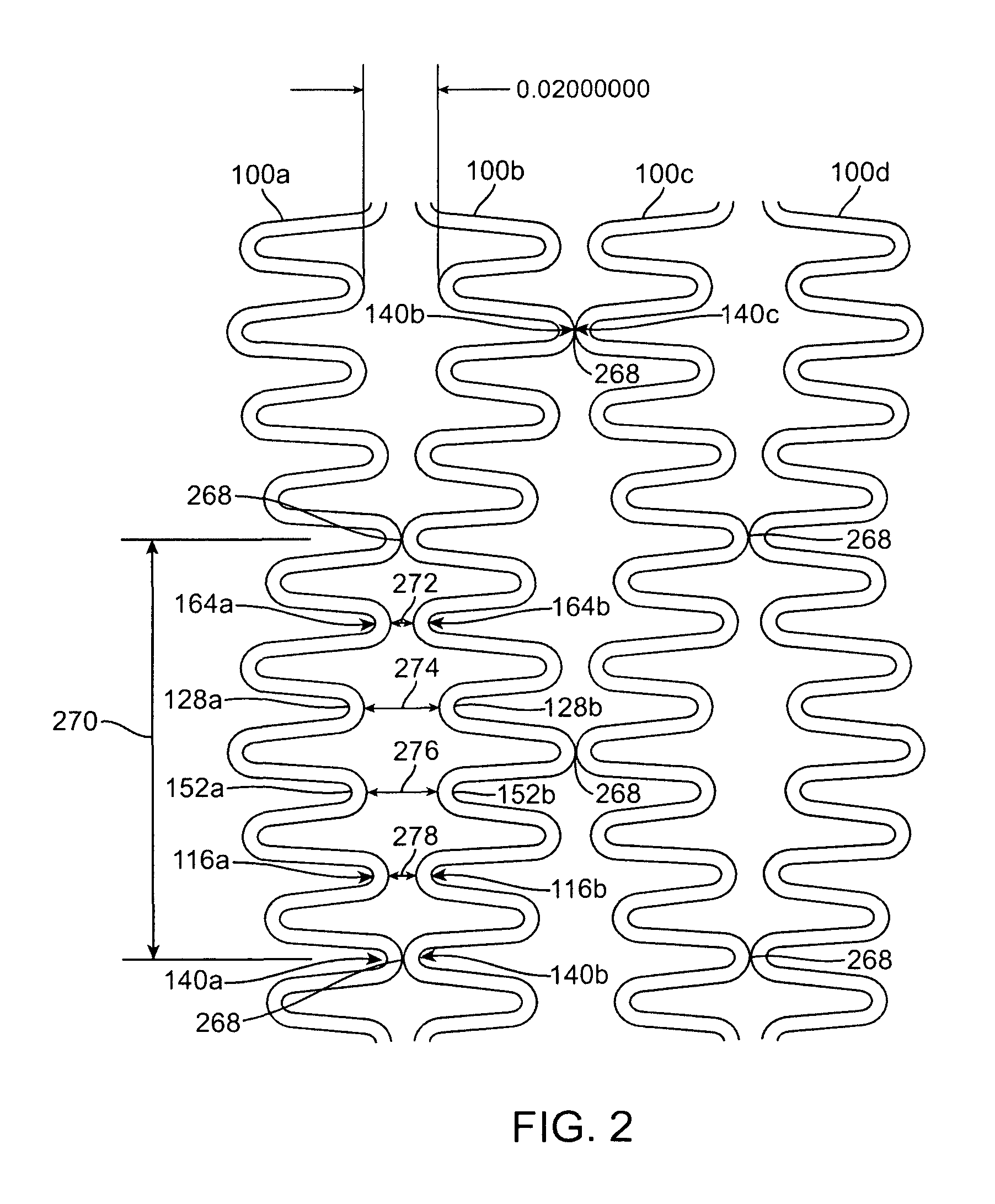
[0028]Specific embodiments of the present invention are now described with reference to the figures, wherein like reference numbers indicate identical or functionally similar elements. The drawing in which an element first appears is typically indicated by the leftmost digit(s) in the corresponding reference number. The terms “distal” and “proximal” are used in the following description with respect to a position or direction relative to the treating clinician. “Distal” or “distally” are a position distant from or in a direction away from the clinician. “Proximal” and “proximally” are a position near or in a direction toward the clinician.

[0029]The following detailed description is merely exemplary in nature and is not intended to limit the invention or the application and uses of the invention. Although the description of the invention is in the context of treatment of blood vessels such as the coronary, carotid and renal arteries, the invention may also be used in any other body p...


PUM


Abstract

A stent made up of at least two connected bands, each band having a pattern of undulations formed from long, short and mid-sized segments connected together by turns. In particular, the pattern includes a repeating series having five segments: a long segment, a short segment, a mid-sized segment, a mid-sized segment, a short segment (LSMMS). When adjacent bands are connected together to form the stent body, the LSMMS segment configuration forms a series of consecutive tapered gaps between the consecutive unconnected close ended turns of adjacent bands which provide greater flexibility for the stent. The series of consecutive tapered gaps allow the stent to flex with little or no interference with adjacent bands when the stent is tracked around a small radius bend in a vessel. In addition, the length of the longest rigid element of the stent is decreased to further improve flexibility. A rigid element is formed by the lengths of the segments on both sides of a connection between adjacent bands. By decreasing the length of this rigid element, the length which must be tracked around the bends of a vessel is shortened and thus the stent is easier to advance.

Description

FIELD OF THE INVENTION[0001]The present invention is directed to intraluminal stents for use in maintaining open collapsed lumen walls, the intraluminal stent having extreme flexibility for being tracked around bends of a vessel having small radii.BACKGROUND OF THE INVENTION[0002]A wide range of medical treatments have been previously developed using “endoluminal prostheses,” which terms are herein intended to mean medical devices which are adapted for temporary or permanent implantation within a body lumen, including both naturally occurring or artificially made lumens. Examples of lumens in which endoluminal prostheses may be implanted include, without limitation: arteries, such as those located within the coronary, mesentery, peripheral, or cerebral vasculature; veins; gastrointestinal tract; biliary tract; urethra; trachea; hepatic shunts; and fallopian tubes. Various types of endoluminal prostheses have also been developed, each providing a uniquely beneficial structure to modi...

Claims


Application Information

Patent Timeline
Patent Type & Authority Patents(United States)
IPC IPC(8): A61F2/06
CPCA61F2/91A61F2/915A61F2002/91516A61F2002/91525A61F2230/0054A61F2002/91575A61F2220/005A61F2220/0058A61F2002/91541
Inventor CRAVEN, MICHAEL
Owner MEDTRONIC VASCULAR INC
Why Eureka
Try Eureka