
Removable dust collecting device for an air conduit

a technology of dust collection device and air conduit, which is applied in the direction of colloidal chemistry, filtration separation, and separation processes, can solve the problems of difficult cleaning inside the ventilation duct, high cost, and limited function range of the robot, and achieve the effect of improving the filtering function of the devi

Inactive Publication Date: 2011-11-08
CHEN DA KAI
View PDF1 Cites 0 Cited by
  • Summary
  • Abstract
  • Description
  • Claims
  • Application Information

AI Technical Summary

Benefits of technology

"The patent describes a device that collects dust and harmful substances from the air in a ventilation duct. The device consists of soft tubes with an adhesive layer that can capture different sizes of substances. Compared to traditional filters, the device has several advantages: it improves the quality of air circulating in the building, it requires no personnel with special training to operate, and it is cost-effective. Additionally, the device can be easily removed and replaced with a new tube when the adhesive layer is no longer effective."

Problems solved by technology

Unlike the conventional design that substance smaller than the filtration hole of the filter can pass easily and harm the person who inhales, the adhesive layer can capture different sizes of substances that contained in the air, improving the quality of air circulating in the building.2. Even though filters provided on conventional ventilation duct or outlets are easily to be removed and cleaned, to clean inside the ventilation duct is a tough task.
However, high cost makes it inconvenient to most medium or small office buildings.
Besides the cost, the function range of the robot is limited by the reception, and since the passage is mostly made of metal, the reception is constantly affected.

Method used


Image

  • Removable dust collecting device for an air conduit
  • Removable dust collecting device for an air conduit
  • Removable dust collecting device for an air conduit

Examples


Embodiment Construction

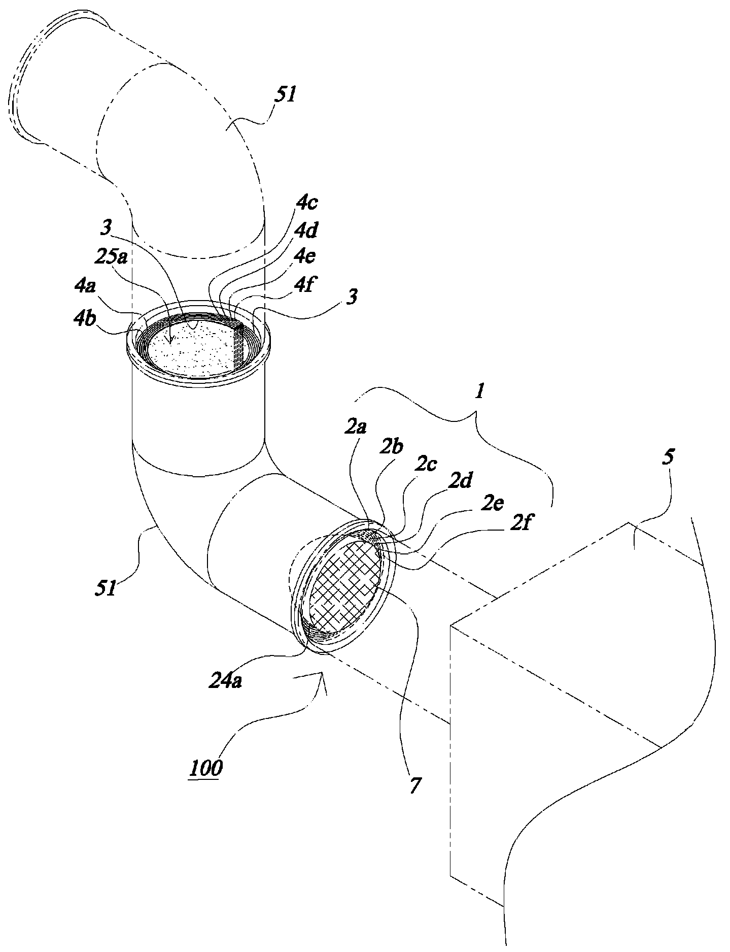
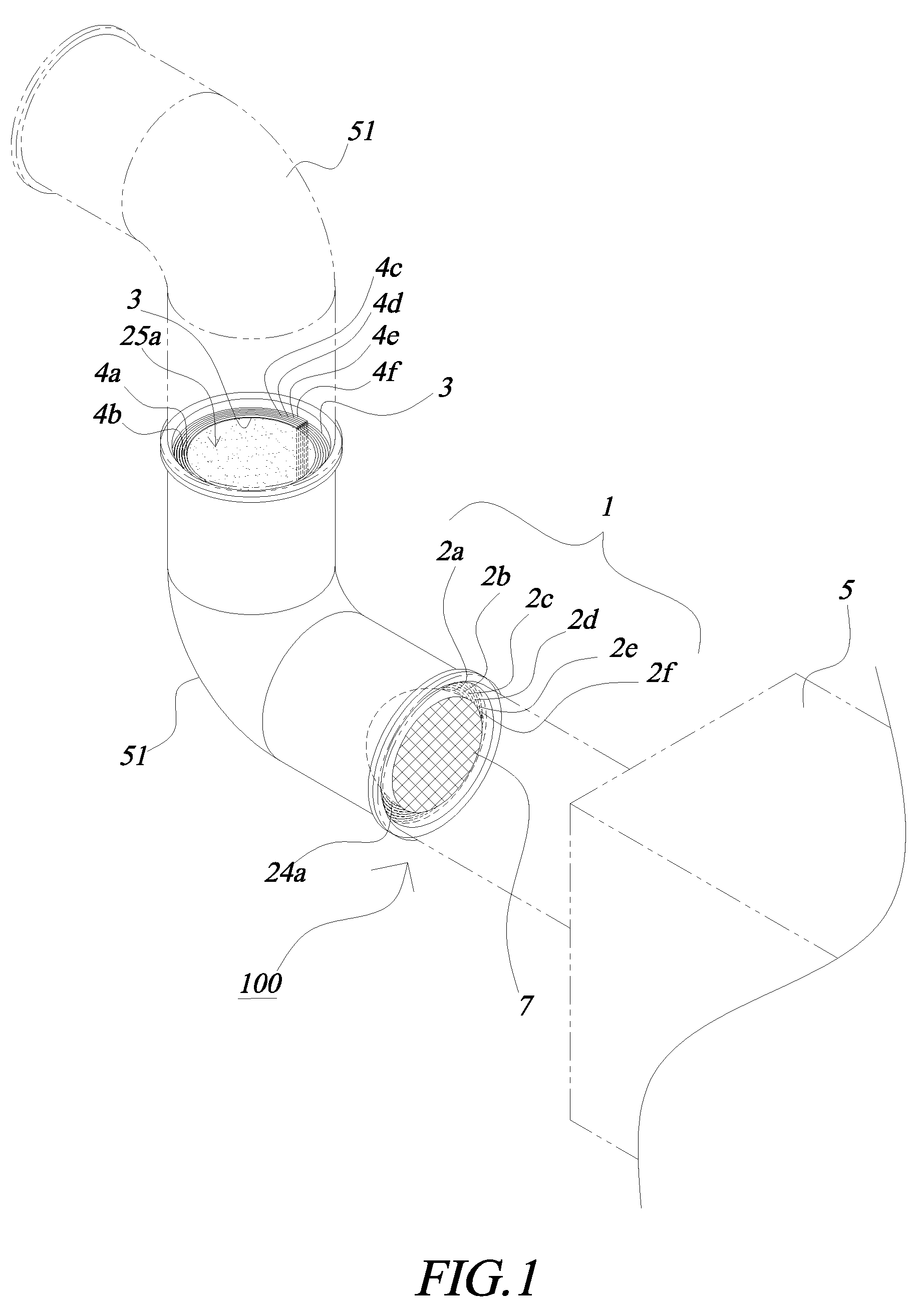
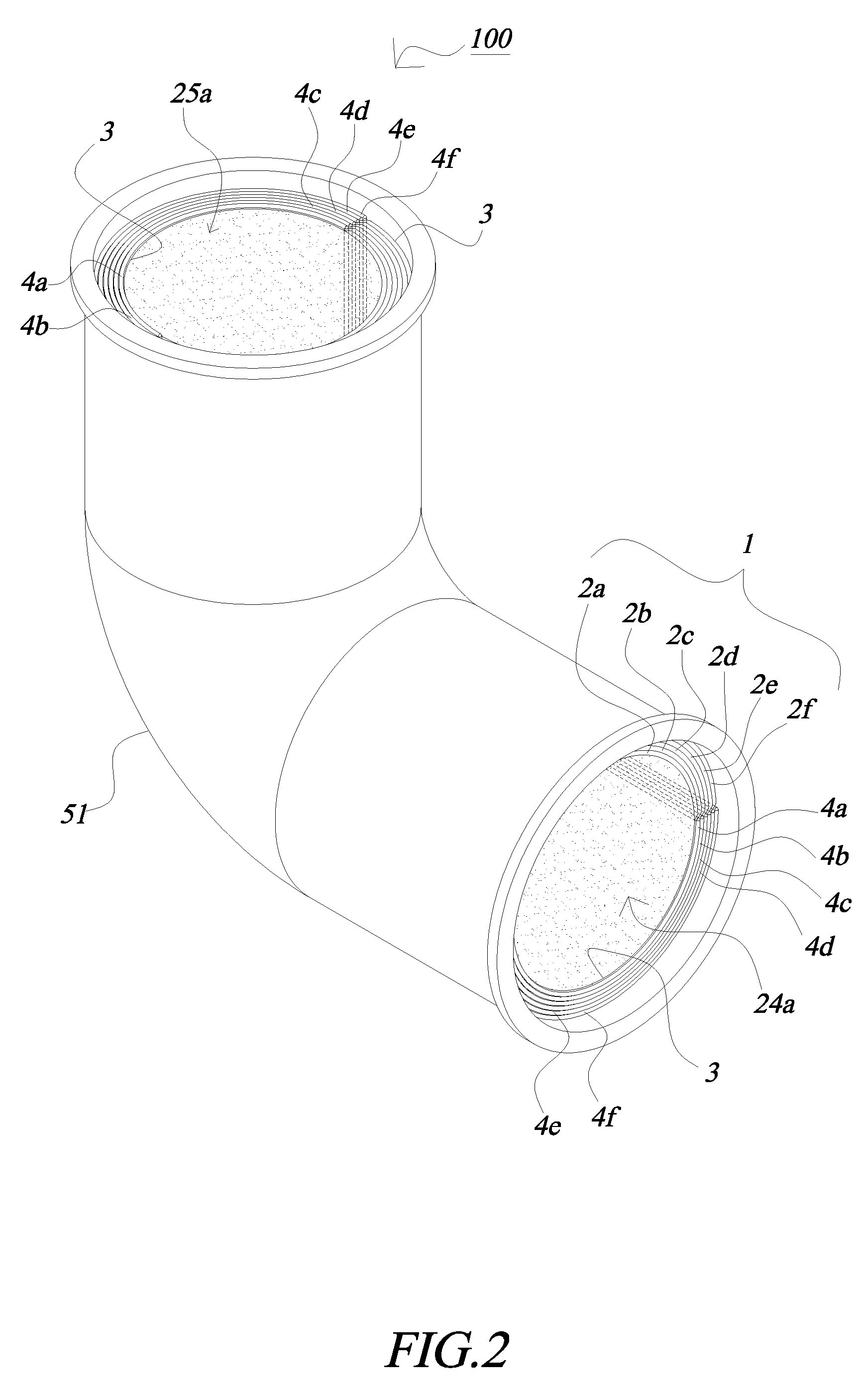
[0016]Referring to FIGS. 1-4 and 7, a removable dust collecting device (100) for an air conduit is characterized in that including a dust collecting tubes set (1). The set (1) is provided about an inner wall of an air conduit (51). Said set (1) consists essentially of a plurality of hollow dust collecting tubes (2a-2f) made of soft material and having different diameters. The dust collecting tubes (2a-2f) are arranged in a concentric fashion by covering the tube having small diameter with another one having larger diameter. Said tubes (2a-2f), after collecting dust to its maximum capacity, are removed from the air conduit (51) sequentially from the smallest diameter.

[0017]An adhesive layer (3) is provided on each inner surface (21a-21f) of said dust collecting tubes (2a-2f) and an outer surface (22f) of the outmost dust collecting tube (2f) for attaching to each other and collecting dust.

[0018]Concentric intakes (24a-24f) with different diameters are provided respectively at an end ...


PUM

PropertyMeasurementUnit
diametersaaaaaaaaaa
diameteraaaaaaaaaa
sizeaaaaaaaaaa

Abstract

A dust collecting device (100) installed inside of an air conduit (51) for collecting airborne particles and for filtrating the air consists of a dust collecting tubes set (1). Said dust collecting tubes set (1) comprises of a plurality of dust collecting tubes (2a-2f) having different diameters. Said tubes (2a-2f) are arranged in a concentric fashion by having a tube with smaller diameter covered by one having larger diameter. Each of said dust collecting tubes (2a-2f) is applied with a layer of adhesive layer (3) for coupling with each other and for adhering particles contained in the air. Each tube of the tube set (1) can be removed from said air conduit (51) by pulling a pull string (4a-4f) provided at two extreme ends of each dust collecting tube (2a-2f).

Description

BACKGROUND OF THE INVENTION[0001]1. Field of the Invention[0002]The present invention relates to a dust collecting device which is set inside an air conduit of a HVAC system for collecting dust and suspended particles contained in the air.[0003]2. Description of Prior Art[0004]A heating, ventilation, air-conditioning and cooling, also known as HVAC, is a system that usually installed in industrial plants, office buildings or skyscrapers for regulating and maintain the air to be safe and health. The regulated air generated by a single or multiples air conditioning devices is transported to each corner of the facilities or buildings through central ventilation duct and multiple sub pipes connected thereto. Even though filters are attached to said air conditioning devices or air outlets for filtering the air, the passages of central ventilation duct or sub pipes are usually difficult to clean due to the size and multiple curve areas, and as time goes by, dust, tiny particles will be ac...

Claims


Application Information

Patent Timeline
Patent Type & Authority Patents(United States)
IPC IPC(8): B01D46/00
CPCB01D46/0012B01D46/10B01D2279/35Y10S55/24
Inventor CHEN, DA-KAI
Owner CHEN DA KAI
Learn More