Method for measuring the saturation rate of an audio amplifier

a saturation rate and audio amplifier technology, applied in the field of audio devices, can solve the problems of reducing the nominal power of the amplifier, signal distortion, and distorted signals, and achieve the effect of accurately measuring the saturation rate of the audio device output amplifier

Active Publication Date: 2011-11-08
STMICROELECTRONICS (GRENOBLE 2) SAS
View PDF9 Cites 2 Cited by
  • Summary
  • Abstract
  • Description
  • Claims
  • Application Information

AI Technical Summary

Benefits of technology

[0015]An embodiment of the present disclosure aims at providing a method enabling to accurately measure the saturation rate of an audio device output amplifier.
[0016]An embodiment of the present disclosure further aims at providing a method enabling to adapt the gain of the output amplifier to the measured saturation.
[0017]One embodiment of the present disclosure enables choosing the best compromise between the useful power transmitted by the application, the distortion of the sound signal, and the speaker protection.

Problems solved by technology

This is regrettable and is contrary to today's miniaturization aims.
A disadvantage of this method is that it decreases the nominal power of the amplifier.
Further, the signal is distorted, even when the amplifier is not saturated.
This protection is further inefficient against strong saturations.
A disadvantage of this type of method is the loss of data as to the amplitude of the audio signal.
Existing solutions for measuring the saturation rate, especially based on measurements of the average level of output voltage VOUT, are inaccurate and introduce delays.

Method used


Image

  • Method for measuring the saturation rate of an audio amplifier
  • Method for measuring the saturation rate of an audio amplifier
  • Method for measuring the saturation rate of an audio amplifier

Examples


Embodiment Construction

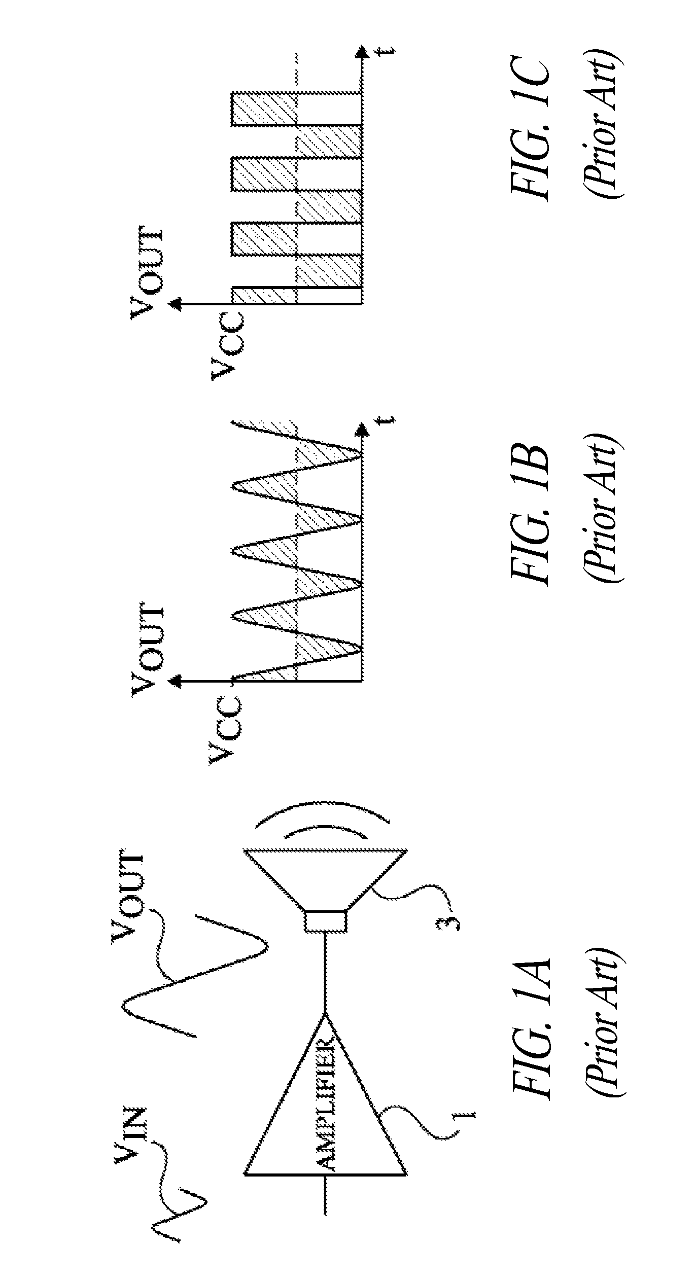
[0043]For clarity, the same elements have been designated with the same reference numerals in the different drawings. Further, the timing diagrams of FIGS. 1A, 1B, 3A to 3C, and 6A to 6C are not drawn to scale.

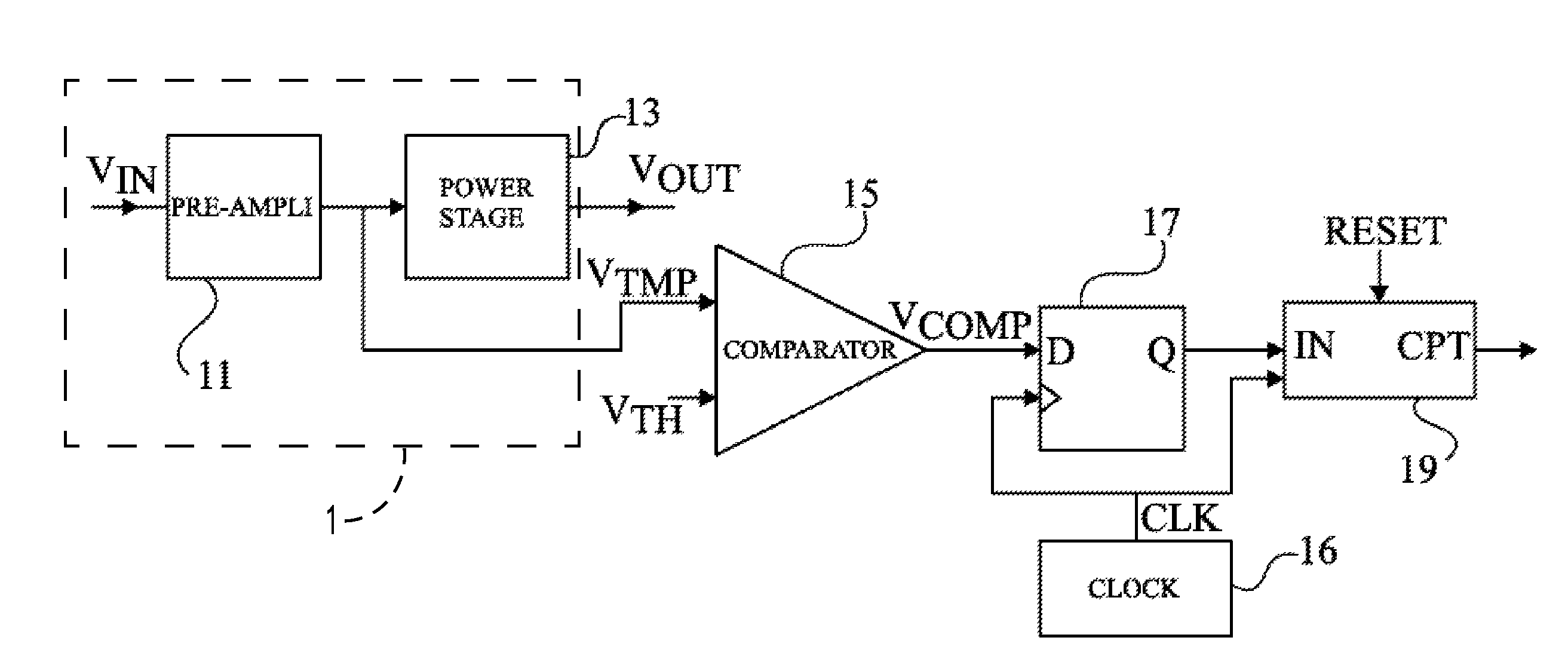
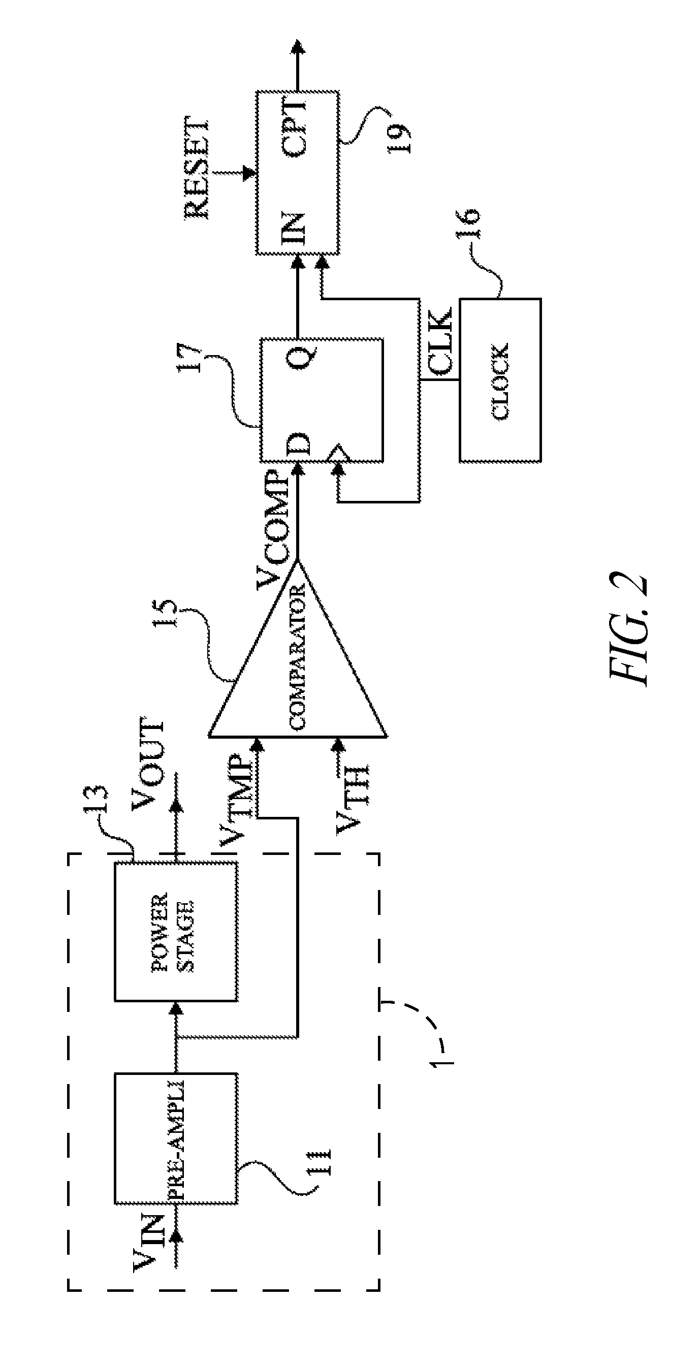
[0044]FIG. 2 shows an example of an audio device output stage. A power amplifier 1 receives an audio signal VIN, generated by upstream stages (not shown), and provides an audio signal VOUT, which is an amplified image of signal VIN. Amplifier 1 is formed of a pre-amplifier stage 11 and of a power stage 13. A comparator 15 receives output signal VTMP of pre-amplifier stage 11 and a D.C. voltage VTH having a level corresponding to a saturation of amplifier 1. A clock signal generator 16 provides a clock signal CLK. A D flip-flop 17, driven by clock signal CLK, receives, via a D input terminal, output signal VCOMP of comparator 15. Flip-flop 17 copies the state (high or low) of its D input on its Q output at each rising edge of clock signal CLK. The Q output of D flip-flop 17 is ...


PUM


Abstract

A method and corresponding circuit that adjusts the gain of an audio output stage having a class D amplifier, this method including the steps of setting the gain to a nominal value, analyzing an output signal during successive clock periods, counting the number of clock periods during which the signal is in a state corresponding to a saturation, decreasing the gain if the number reaches, before the end of a first time interval, a value corresponding to a first percentage, maintaining the gain constant if, at the end of a second time interval, different from the first interval, the number corresponds to a second percentage being comprised between the first percentage and a third percentage, and increasing the gain if, at the end of the second time interval, the number corresponds to a fourth percentage, lower than the third percentage.

Description

BACKGROUND[0001]1. Technical Field[0002]The present disclosure relates to audio devices especially utilizing an output amplifier connected to a speaker, the output amplifier capable of entering a saturation state.[0003]2. Description of the Related Art[0004]An audio device generally includes upstream stages, the main function of which is to process or to decode and to pre-amplify an audio signal stored in any support, for example, an internal memory, an optical disk, or any incident audio signal, and an output power amplifier, having the function of generating an analog audio signal adapted to output speakers.[0005]FIG. 1A schematically shows the terminal portion of an audio device. An amplifier 1 receives an audio signal VIN, generated by upstream stages, and delivers an audio signal VOUT, which is an amplified image of signal VIN, to a speaker 3 of a known configuration. Amplifier 1 has a maximum output amplitude VCC determined by its supply voltage.[0006]FIGS. 1B and 1C show exam...

Claims


Application Information

Patent Timeline
Patent Type & Authority Patents(United States)
IPC IPC(8): H03F3/217
CPCH03G7/002H03G11/00
Inventor RABARY, VINCENTCITTADINI, ROBERTHUFFENUS, ALEXANDREPILLONNET, GAEL
Owner STMICROELECTRONICS (GRENOBLE 2) SAS
Why Eureka
Try Eureka