Shoe system with a resilient shoe insert

a shoe system and resilient technology, applied in the field of resilient shoe spring system, can solve the problems of reducing the biomechanical effect, affecting so as to improve the walking and running economy, improve the stability and cushioning of the biomechanical shoe, and increase the thickness of the shoe sol

Active Publication Date: 2011-11-15
LUBRIZOL ADVANCED MATERIALS INC +1
View PDF15 Cites 26 Cited by
  • Summary
  • Abstract
  • Description
  • Claims
  • Application Information

AI Technical Summary

Benefits of technology

[0004]The method and shoe system of the present invention provide a solution to the above-mentioned problems. For instance will it not only provide sufficient chock absorption / cushioning in order to protect users from injuries related to the stresses of prolonged standing, walking and running. It will also, by its function of storing up energy, provide sufficient energy to heave up the user out of the cushioning, i.e. it does not only absorb energy, it also gives back energy. Furthermore, it does so without risking almost immediate fatigue failure of the resilient shoe insert which is the case with corresponding non-progressive inventions. More particularly, the method is for using a shoe system having a resilient shoe insert. A shoe has a shoe insert disposed inside the shoe. The insert has an upper leg and a lower leg connected by a front end with a curvature. The upper and lower legs 506 have a concave segments and end points. A load is put on the insert to compress the end points towards one another. This shortens the effective length of the legs because the legs are in contact at a contact segment. This makes the insert stiffer the more it is compressed. The effective length of the legs is shorter at the outside compared to the inside so that the outside is stiffer than the inside.

Problems solved by technology

This has resulted in a slight change of the angle between the ankle and the foot that may weaken the tendons of the foot.
This change of the angle may also lead to instability and reduced bio-mechanical effect.
In addition, the focus on increasing the chock absorption within the shoe industry has led to yet another problem, namely the fact that the more cushioning put into a shoe the more energy is needed to get out of it.
However, the earlier proposed spring designs for shoe soles have not been satisfactory.
Despite many elaborate shoe sole solutions, back injuries and other injuries are still common due to poorly designed shoes.
This shortens the effective length of the legs because the legs are in contact at a contact segment.
Without the wave-profile of the wings, there was no way of taking-off with the airplane.

Method used


Image

  • Shoe system with a resilient shoe insert
  • Shoe system with a resilient shoe insert
  • Shoe system with a resilient shoe insert

Examples


second embodiment

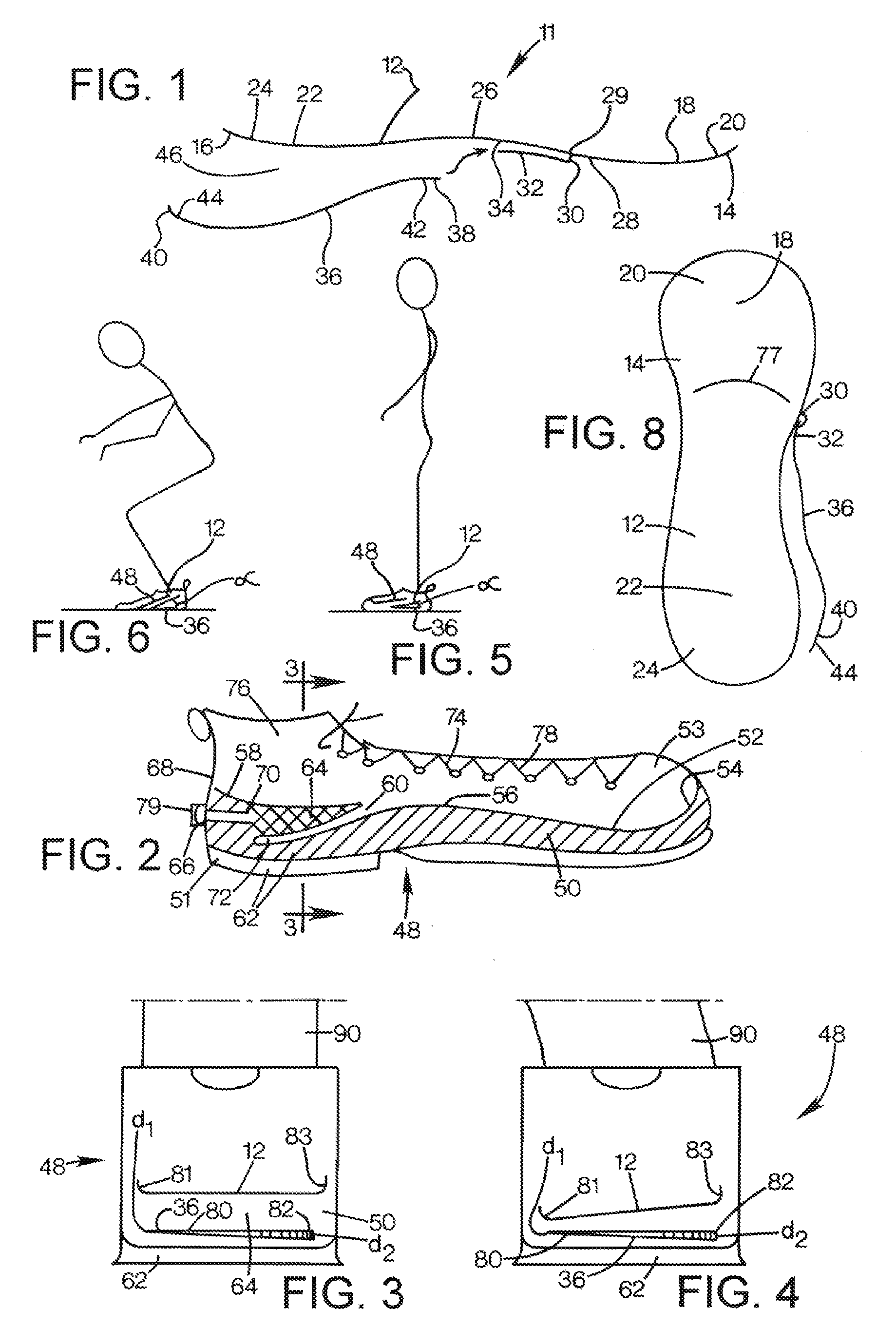
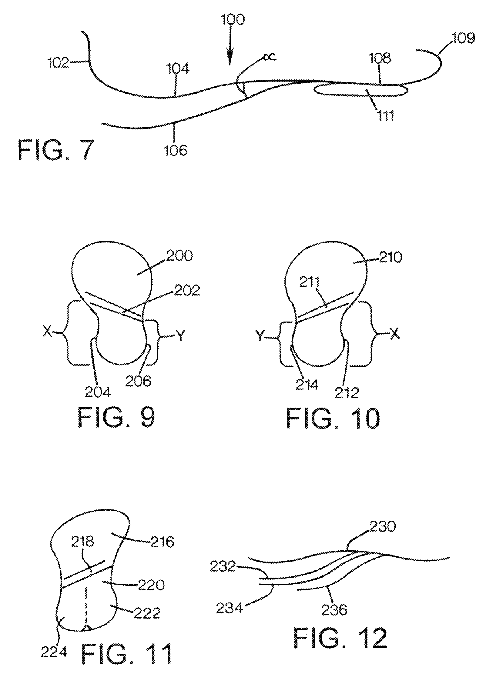
[0041]FIG. 9 is a top view of the shoe insert of the present invention. A shoe insert 200 has a transition area 202 (that is equivalent to the transition area 77 of FIG. 8) that extends at an angle so that a distance (x) at an inside 204 of the shoe insert 200 is longer than a distance (y) at an outside 206. In other words, the flexible member is longer at the inside 204 than the outside 206 so that the inside 204 may flex (as shown in FIG. 4) while the outside 206 is relatively stiff. Similarly, FIG. 10 shows a top view of a shoe insert 210 for the left shoe that has a transition area 211 and an inside 212 that has a length (x) that is longer than a length (y) of an inside 214. FIG. 11 is a bottom view of a third embodiment of the present invention.

third embodiment

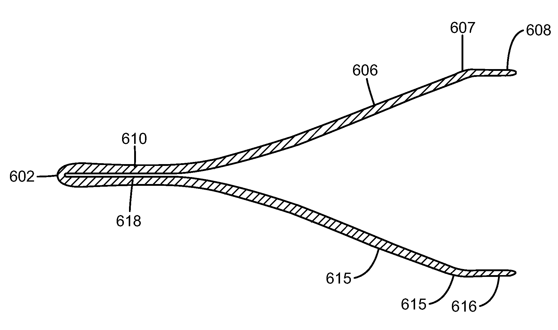
[0042]A shoe insert 216 has an angular transition area 218 in addition to a flexible member 220 that has a softer inside portion 222 and a stiffer outside portion 224. In the third embodiment, it is not necessary that the transition area extends at an angle because the inside portion 222 is already softer than the outside portion 224. FIG. 12 is a side view of a shoe insert 230 having a plurality of flexible members 232, 234, 236 attached to an underside 238 of the shoe insert 230 so that both the resiliency and the resiliency on the inside and the outside may be adjusted to the specific needs of the user of the shoe insert 230.

fifth embodiment

[0043]FIGS. 13 and 14 show the present invention. A shoe 300 has a shoe sole 302 including an upper layer 303 with a shoe insert 304 integrated with or built into the sole 302. The shoe 300 has a toe portion 330 and a heel portion 332 and shoe sole 302 has a bottom side 305. The insert 304 has a relatively stiff upper segment 306 and a bendable lower segment 308 that is attached to a lower side 310 of the segment 306 at a mid-section 312 of the upper segment 306. The segment 306 is, preferably, attached to a back piece 301 that is disposed at the upper segment 303 adjacent to a backside 309 of the shoe 300. The upper segment 306 and the lower segment 308 have a space 307 defined therebetween. The space 307 may be filled with air or a very compressible and expandable material. The space 307 may be completely or partially filled with a material. For example, the material may include segments of an elastomeric material to change the spring characteristics of the insert 304. Stiffer ela...


PUM


Abstract

A first load (L1) is put on the upper leg (606) to create a contact area (619) between the front segment (610) and the front segment (618). The contact area (619) has a center point (601) located a distance (p1) from the front end (602). An upper forward segment (621) pulls away from a lower forward segment (623) immediately adjacent to the front end (602) to create a loop (625a). The first load (L1) is progressively increased to a second load (L2) and the center point (601) is rolled back from the distance (p1) to a distance (p2) from the front end (602). The segments (621) and (623) expand the loop (625a) to a loop (625b).

Description

TECHNICAL FIELD[0001]The present invention relates to a resilient shoe spring system that is integrated with a shoe system. In comparison with previous inventions within this field, it introduces progressiveness along with new features as pull and roll factors.BACKGROUND AND SUMMARY OF THE INVENTION[0002]Users and developers of elastic shoes and shoe soles are confronted with the problem of back injury and releasing the stored energy in the shoe sole in a manner which improves walking and running economy while at the same time achieving adequate bio-mechanical shoe stability and cushioning. Many shoe manufacturers have concentrated their effort on chock absorption by permanently increasing the thickness of the shoe sole. This has resulted in a slight change of the angle between the ankle and the foot that may weaken the tendons of the foot. This change of the angle may also lead to instability and reduced bio-mechanical effect. In addition, the focus on increasing the chock absorpti...

Claims


Application Information

Patent Timeline
Patent Type & Authority Patents(United States)
IPC IPC(8): A43B13/18A43B13/14
CPCA43B13/026A43B13/12A43B13/183A43B13/187A43B13/203A43B13/127
Inventor LINDQVIST, WILHELM OVELARSSON, HANSLINDH, LEIFLINDH, KJELL
Owner LUBRIZOL ADVANCED MATERIALS INC
Why Eureka
Try Eureka