Pressure device for a variable compression ratio engine

a pressure device and compression ratio technology, applied in the direction of positive displacement engines, reciprocating piston engines, engine controllers, etc., can solve the problems of high temperature differences between the top and bottom parts affecting the operation of the control rack, and requiring a high degree of precision in the production of the cylinder block and/or the adjustment shim, etc., to achieve the effect of increasing the volumetric ratio and speeding up the movement of the control rack

Active Publication Date: 2011-11-15
MCE 5 DEV 72 PART INTEREST
View PDF8 Cites 1 Cited by
  • Summary
  • Abstract
  • Description
  • Claims
  • Application Information

AI Technical Summary

Benefits of technology

[0024]the speed of movement of the control rack in the sense of increasing the volumetric ratio is increased.

Problems solved by technology

The maximum operating clearance between the toothings of the large-sized racks and the toothings of the toothed wheel can be adjusted in various ways which all have the disadvantage of requiring a high degree of precision in the production of the cylinder block and / or of adjustment shims.
This is because said parallelism defects can lead to the moving components jamming inside said cylinder block when the engine is operating.
High temperature differences can also occur in operation between the top and bottom parts of the cylinder block.
Another production difficulty stems from the need to reduce as far as possible the operating clearance between the jack piston which actuates the control rack and its bore in order to limit the acoustic emissions of the engine.
Moreover, another defect relating to the operation of the control rack by the control jack will be noted: said operation takes place less quickly to increase the volumetric ratio than to lower it.

Method used


Image

  • Pressure device for a variable compression ratio engine
  • Pressure device for a variable compression ratio engine
  • Pressure device for a variable compression ratio engine

Examples


Embodiment Construction

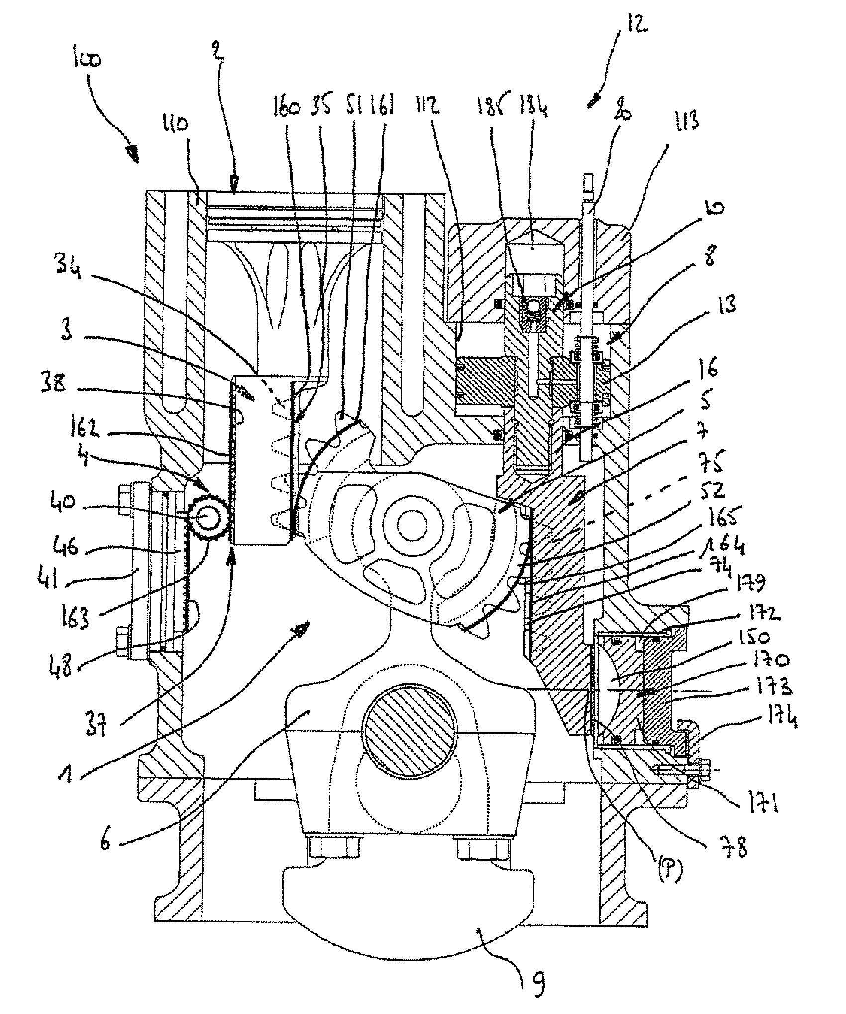
[0071]FIG. 1 shows an engine block 100 which comprises at least one cylinder 110, in which a piston 2 moves by means of a transmission device 1, and pressure means which make it possible to maintain in position the main moving components of a variable volumetric ratio engine in their cylinder block.

[0072]In the lower portion of the piston 2, the mechanical transmission device 1 comprises a transmission member 3 secured to said piston and cooperating, on the one hand, with a rolling guide device 4 and, on the other hand, with a toothed wheel 5.

[0073]The toothed wheel 5 cooperates with a connecting rod 6 connected to a crankshaft 9 in order to transmit the movement between the piston 2 and said crankshaft.

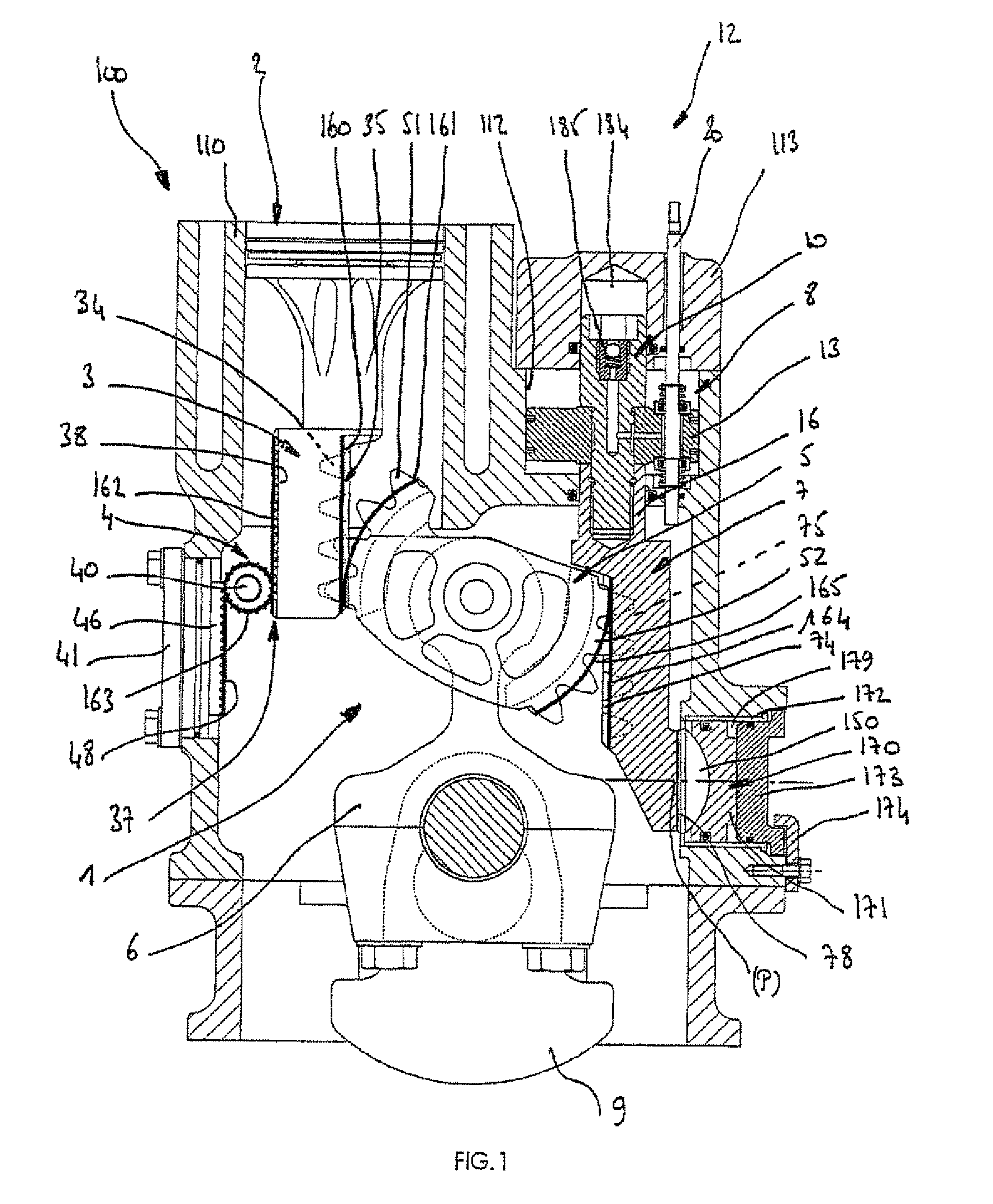
[0074]On the opposite side to the transmission member 3, the toothed wheel 5 cooperates with another rack, termed control rack 7, of which the vertical position with respect to the engine block 100 is governed by a control device 12 comprising a control jack 8, the jack piston 13 of ...


PUM


Abstract

A pressure device maintains the raceways (48, 160 to 165) of the main moving components (3, 5, 7 and 40) of a variable compression ratio engine permanently in contact with one another and with the faces on which they rest in a cylinder case. The inventive device includes pressure elements which are solidly connected to the cylinder case (100) and which exert a pressure force on a control rack (7) having a toothed segment (75) formed by teeth (74). The pressure force is applied against a support surface (78) provided on the lower part of the rack (7).

Description

BACKGROUND OF THE INVENTION[0001]1. Field of the Invention[0002]The present invention relates to a pressing device which maintains the raceways of the main moving components of a variable volumetric ratio engine permanently in contact with one another and with the faces on which they bear in the cylinder block.[0003]2. Description of the Related Art[0004]International patents WO98 / 51911, WO00 / 31377, WO03 / 008783, belonging to the Applicant, disclose various mechanical devices for a variable volumetric ratio engine.[0005]It will be seen that international patent WO98 / 51911, in the name of the Applicant, describes a device which serves to improve the overall efficiency of internal combustion piston engines used at variable load and speed by adapting their effective displacement and / or their volumetric ratio during operation.[0006]It will be observed from international patents WO00 / 31377 and WO03 / 008783, in the name of the Applicant, that the mechanical transmission device for a variabl...

Claims


Application Information

Patent Timeline
Patent Type & Authority Patents(United States)
IPC IPC(8): F02B75/04
CPCF01B9/047F16C5/00F02B75/048F02B75/045F02B75/04F01B9/04
Inventor RABHI, VIANNEY
Owner MCE 5 DEV 72 PART INTEREST
Why Eureka
Try Eureka