System and method for providing electrochemical machining of a device

a technology of electrochemical machining and machining system, which is applied in the direction of machining electric circuits, manufacturing tools, power source circuits, etc., can solve the problems of inaccuracy of geometry, permanent damage to the blades of the bladed parts, and unaddressed needs in the industry

Active Publication Date: 2011-11-15
TURBOCAM
View PDF9 Cites 18 Cited by
  • Summary
  • Abstract
  • Description
  • Claims
  • Application Information

AI Technical Summary

Problems solved by technology

Unfortunately, improper electrochemical machining may result in inaccurate geometry and permanent damage to the blades of the bladed part.
Thus, a heretofore unaddressed need exists in the industry to address the aforementioned deficiencies and inadequacies.

Method used


Image

  • System and method for providing electrochemical machining of a device
  • System and method for providing electrochemical machining of a device
  • System and method for providing electrochemical machining of a device

Examples


Embodiment Construction

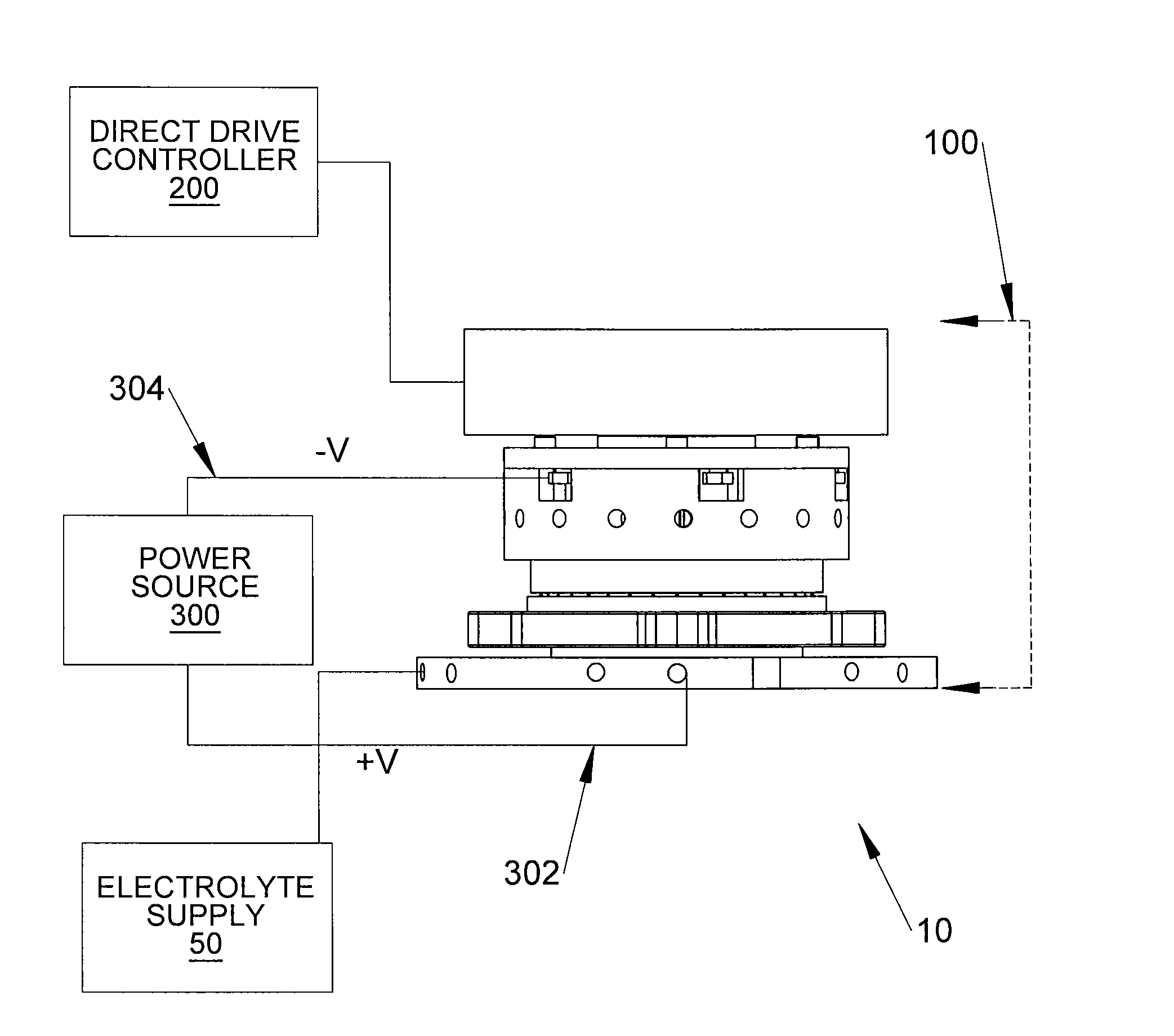
[0030]The present system and method provides for the electrochemical machining of a device, also referred to herein as a work-piece. Among other portions, the present system contains a fixture, a rotary drive subassembly, and a rotary drive assembly. A work-piece is positioned and secured to the fixture, after which the rotary drive subassembly is positioned to achieve initial machining gap. The subassembly outer shell creates a seal for the electrolyte. An electrolyte flows through the system, thereby completing a circuit between the work-piece and the subassembly. Blades of the work-piece may be electrochemically machined during completion of the circuit in accordance with motion of the rotary drive subassembly. Motion of the rotary drive subassembly is managed by a direct drive controller, which controls frequency and amplitude of a control signal provided to the system for precisely increasing and decreasing rotational motion of the rotary drive subassembly.

[0031]FIG. 1 is a sch...


PUM

PropertyMeasurementUnit
frequencyaaaaaaaaaa
voltageaaaaaaaaaa
mechanical oscillationaaaaaaaaaa

Abstract

A system and method for electrochemically machining a work-piece contains a fixture capable of receiving a work-piece and securing the work-piece to the fixture. An electrolyte source is also provided. In addition, the system contains a rotary drive subassembly capable of receiving a portion of the work-piece therein, motion of the rotary drive assembly being determined by a received control signal, wherein frequency and amplitude of the control signal increases and decreases motion of the rotary drive subassembly, and wherein the control signal is a trapezoidal waveform.

Description

FIELD OF THE INVENTION[0001]The present invention is generally related to electrochemical machining, and more particularly is related to a system and method for providing electrochemical machining of a device such as, but not limited to, airfoils, turbocharger nozzle rings and blisks.BACKGROUND OF THE INVENTION[0002]Electrochemical machining is a well-known process used for the machining of a workpiece. In a typical electrochemical machining process, a workpiece is typically provided with a positive voltage to create an anode portion, and an electrode is provided with a negative voltage to create a cathode portion. An electrolyte is provided in a gap between the workpiece and the electrode for electrochemical machining of the workpiece.[0003]As is known in the art, the gap between the anode portion and the cathode portion needs to be closely monitored and maintained in order to prevent touching of the cathode portion and the anode portion and also to maintain machined form and toler...

Claims


Application Information

Patent Timeline
Patent Type & Authority Patents(United States)
IPC IPC(8): B23H3/00
CPCB23H7/18B23H7/30B23H11/003B23H9/10B23H2300/10
Inventor MCGEE, THOMAS S.NORONHA, MARIAN B.WOLTERS, HANS HENDRIK
Owner TURBOCAM
Why Eureka
Try Eureka