Acoustic airport surveillance system

a technology of acoustic airports and surveillance systems, applied in the field of monitoring systems, can solve the problems of acoustic airport surveillance systems that may only be implemented in large airports, controllers only a few seconds to respond, and the type of sensing systems that offer limited capabilities and provide a small amount of time for air traffic controllers to respond

Active Publication Date: 2011-11-15
THE BOEING CO
View PDF9 Cites 49 Cited by
  • Summary
  • Abstract
  • Description
  • Claims
  • Application Information

AI Technical Summary

Problems solved by technology

These radar systems may only be implemented in large airports due to the high cost of these systems.
While these systems may provide detection of moving aircraft within an airport environment, some airports may have sensing gaps where the aircraft operating on a runway or taxiway may go undetected.
In addition, these sensing systems require the aircraft to actually move before they can detect and alert human air traffic controllers of potential runway incursions.
This gives controllers mere seconds to respond to a detected movement that may pose a potential runway conflict.
This type of sensing system offers limited capabilities that provide a small amount of time for air traffic controllers to respond.
Additionally, many airport environments may not possess the resources to acquire and implement expensive radar systems, and must rely on visual detection by human air traffic controllers.

Method used


Image

  • Acoustic airport surveillance system
  • Acoustic airport surveillance system
  • Acoustic airport surveillance system

Examples


Embodiment Construction

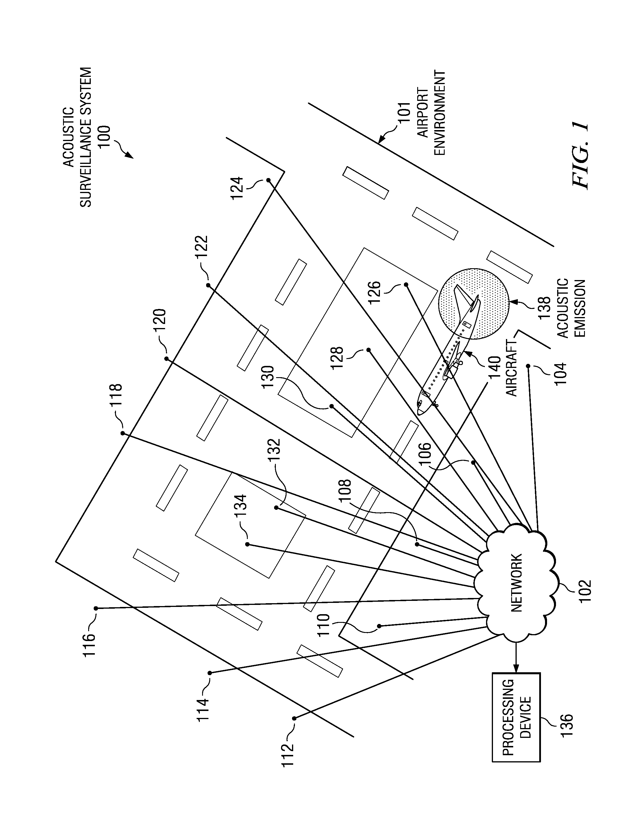
[0022]With reference now to the figures and in particular with reference to FIG. 1, an illustration of an acoustic surveillance system is depicted in accordance with an advantageous embodiment. Acoustic surveillance system 100 may be implemented in a number of different environments. In this illustrative example, acoustic surveillance system 100 is implemented in airport environment 101. Acoustic surveillance system 100 may be used to detect a vehicle in an environment, such as airport environment 101. A vehicle may be, without limitation, an aircraft. An aircraft may include, for example, without limitation, an airplane, helicopter, unmanned aerial vehicle, and / or other air vehicles.

[0023]Acoustic surveillance system 100 may be implemented in a network environment including network 102. In these illustrative examples, network 102 may include a number of different media for transmitting data to processing device 136. This media may include, for example, the internet, wireless transm...


PUM

PropertyMeasurementUnit
frequencyaaaaaaaaaa
bearing versus timeaaaaaaaaaa
versus timeaaaaaaaaaa

Abstract

The different advantageous embodiments provide a method and apparatus for detecting an aircraft. The different advantageous embodiments may provide a method for detecting an acoustic emission emitted by the aircraft using a number of acoustic sensors to form a detected acoustic emission. The aircraft may be identified from the detected acoustic emission to form an identified aircraft. A bearing may be estimated for the identified aircraft using the detected acoustic emission.

Description

BACKGROUND INFORMATION[0001]1. Field[0002]The present disclosure relates generally to monitoring systems and in particular to a method and apparatus for surveillance of aircraft in an airport environment. Still more particularly, the present disclosure relates to a method and apparatus for detecting, tracking and classifying aircraft using sound sensors distributed across a surveillance area.[0003]2. Background[0004]An ability to detect and track aircraft in an airport environment is an important capability for areas where ground surveillance radars do not exist or are limited in detection scope. Today, air traffic control radar systems are used to attempt to track and identify aircraft moving within an airport environment, such as on a runway or taxiway. These radar systems may only be implemented in large airports due to the high cost of these systems.[0005]While these systems may provide detection of moving aircraft within an airport environment, some airports may have sensing ga...

Claims


Application Information

Patent Timeline
Patent Type & Authority Patents(United States)
IPC IPC(8): G01N29/14G01S1/00G01S3/80
CPCG01N29/14G01N29/46G01S3/803G01N2291/2694
Inventor LEE, JONATHAN S.NIELSEN, RICHARD O.DAVIS, HENRY HOOPERDUNHOLTER, PAUL H.
Owner THE BOEING CO
Why Eureka
Try Eureka