Sheet metal bending machine and production line incorporating a machine of this type

a technology of metal bending machine and production line, which is applied in metal rolling, manufacturing tools, counter-pressure devices, etc., can solve the problems of bending rollers beginning to become twisted, bending rollers tending to present deflection, and presenting significant deflection

Inactive Publication Date: 2011-11-22
CONCEPTION MACHINES FAVEYRIAL
View PDF5 Cites 7 Cited by
  • Summary
  • Abstract
  • Description
  • Claims
  • Application Information

AI Technical Summary

Benefits of technology

[0012]Such a roll bender makes it possible to compensate in coordinated manner for the deflections of the various rollers, and thus to form tubes that are cylindrical.

Problems solved by technology

Given the stresses to which it is subjected during a rolling operation, a bending roller of this diameter, having a length close to one meter, does not remain rectilinear, but tends to present significant deflection.
Similarly, the backing rollers tend to present deflection.
Depending on the stresses exerted by the metal sheet, this problem of deflection can also be accompanied by the bending roller beginning to become twisted.
The amount of compensation is not under control, and deflection of the bending roller is not compensated at all.
Such a system does not enable tubes to be obtained that are genuinely cylindrical with a diameter close to 80 mm and a length close to 1.20 m.

Method used


Image

  • Sheet metal bending machine and production line incorporating a machine of this type
  • Sheet metal bending machine and production line incorporating a machine of this type
  • Sheet metal bending machine and production line incorporating a machine of this type

Examples


Embodiment Construction

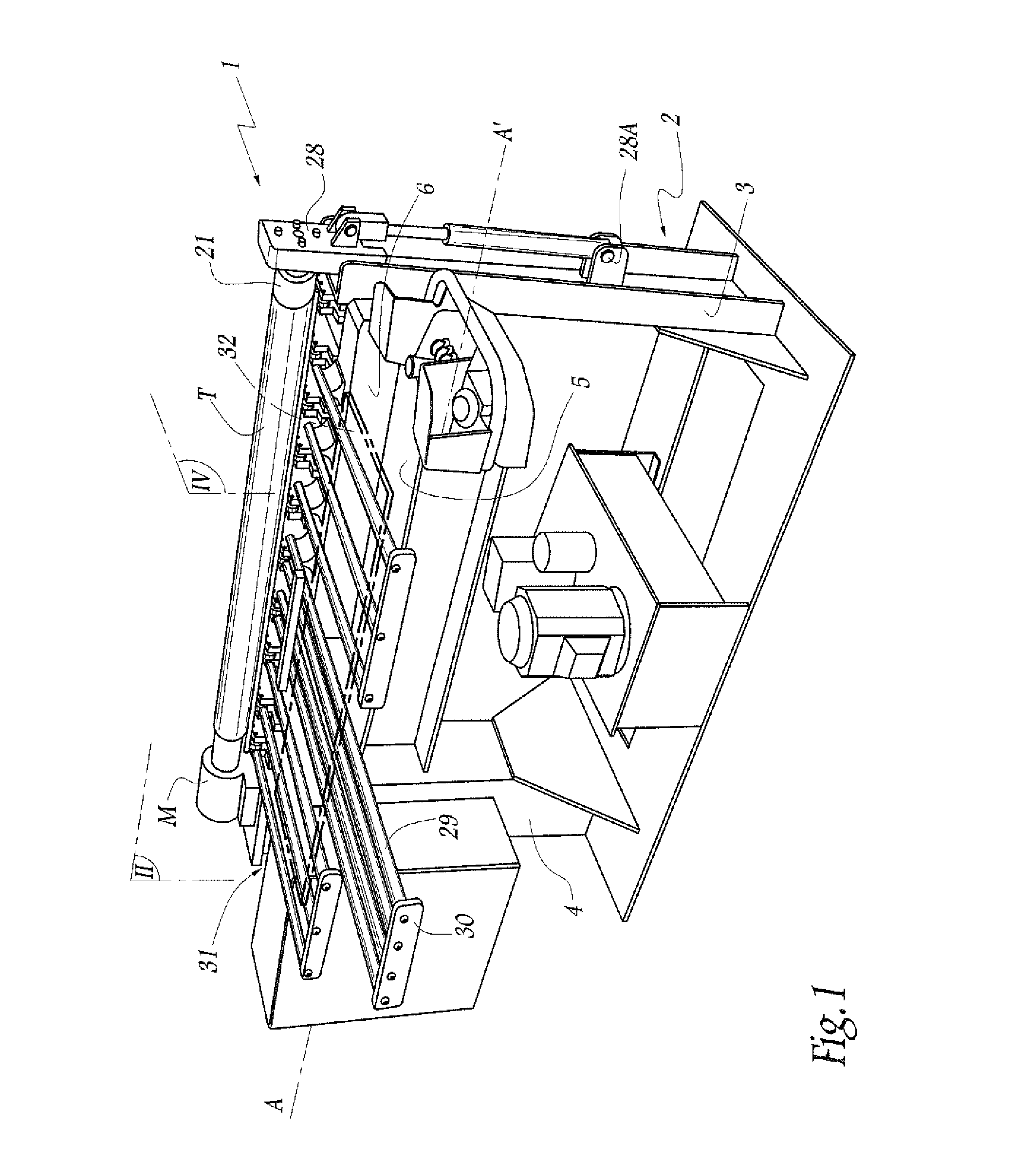
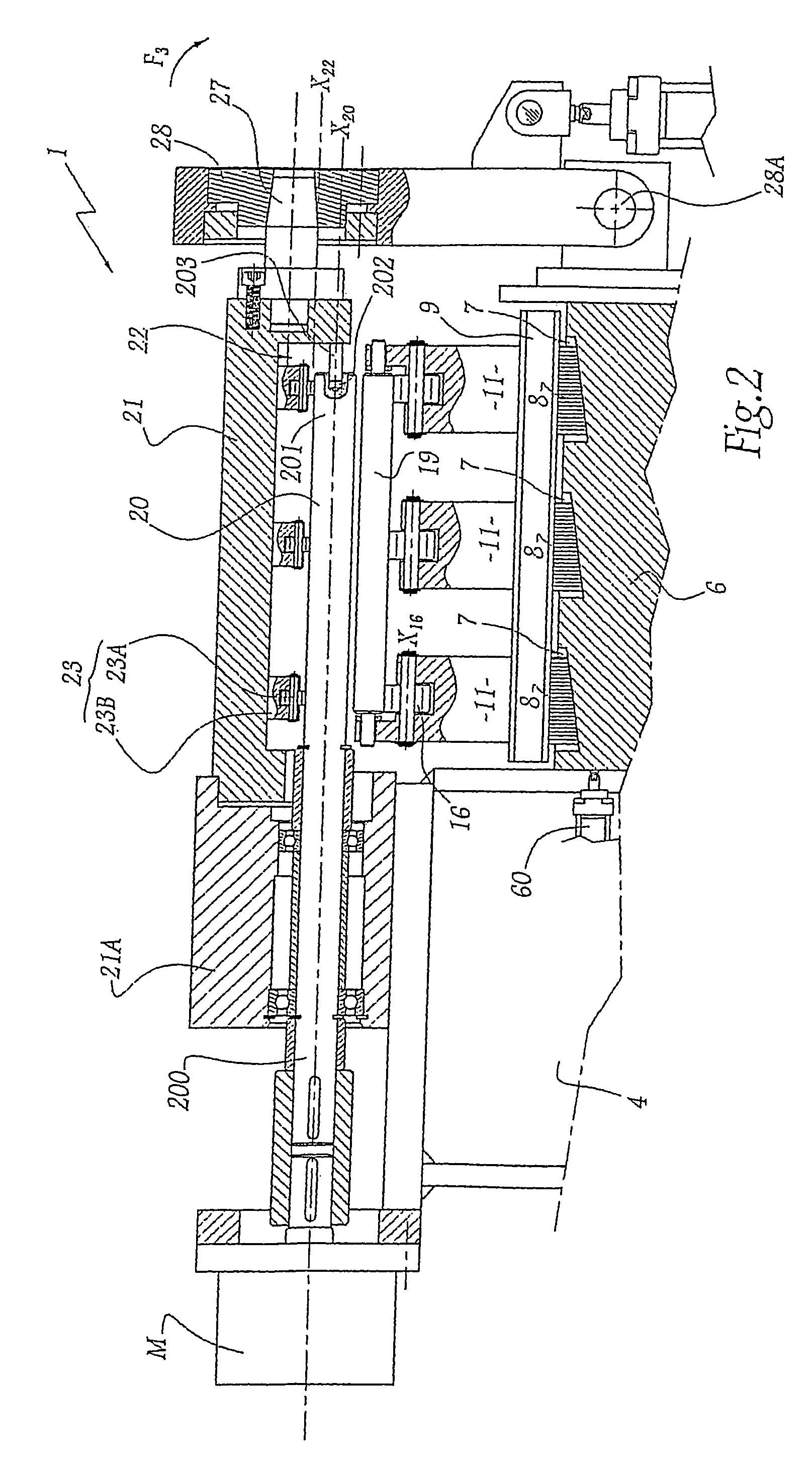
[0030]The sheet metal bending machine 1, known as a “roll bender”, shown in FIG. 1 comprises a main body 2 that is generally H-shaped. The spacing between the uprights 3 and 4 of the H-shape is adapted to the final length of the tube T that it is desired to make. The transverse bar or beam 5 of the body 2 of the machine supports a stationary crossbar 6 that is held generally horizontal. The crossbar 6 is provided on its top face with three notches 7 that are inclined at about 45° relative to a longitudinal axis A-A′ of the beam 5. The crossbar 6 is movable longitudinally by a hydraulic device 60 in a direction parallel to the axis A-A′.

[0031]A second crossbar 9 fitted on its bottom face with at least two spacers 8 is placed on the crossbar 6. Thus, when the crossbar 6 is moved simultaneously with the spacers 8 from right to left or from left to right in FIG. 2, the crossbar 6, the spacers 8 slide on the slope of the notches 7 on which they rest and cause the crossbar 9 to move up or...


PUM

PropertyMeasurementUnit
thicknessaaaaaaaaaa
lengthaaaaaaaaaa
diameteraaaaaaaaaa

Abstract

A roll bender machine for bending metal sheets which includes a roller driven in rotation and about which the sheet metal is rolled and at least two backing rollers adapted to receive and bear against a sheet while it is being bent around the roller. The backing rollers are mounted to rotate on a support that is adjustable. The bending roller and backing rollers are each associated with at least one set of devices for compensating their deflection. An arm is mounted on the machine for receiving coiled sheet metal and is provided with a housing in which the bending roller is at least partially received.

Description

BACKGROUND OF THE INVENTION[0001]1. Field of the Invention[0002]The invention relates to a machine for bending metal sheets, and more particularly to a machine of the roll bender type. The invention also relates to a line for fabricating tubes or cylinders by bending sheets, the installation incorporating a bending machine. The term “roll bender” designates any machine enabling a tube or ferrule to be made from a metal plate of small thickness, in particular a metal sheet. Tubes or ferrules are made from sheets by bending, i.e. the sheet is curved about a radius of curvature corresponding to that of the tube or the ferrule. In particular, the invention relates to roll benders for making tubes or ferrules of diameter that is as small as possible as a function of the length of the tube and the thickness of its wall, for example tubes having a diameter of 60 millimeters (mm) for a length of about 1 meter (m), and a thickness of 0.5 mm.[0003]2. Description of the Related Art[0004]FR-B-2...

Claims


Application Information

Patent Timeline
Patent Type & Authority Patents(United States)
IPC IPC(8): B21D5/14B21D9/10
CPCB21D5/14
Inventor GRAVIER, MICHEL
Owner CONCEPTION MACHINES FAVEYRIAL
Why Eureka
Try Eureka