Variable valve actuating apparatus for internal combustion engine and control shaft for variable valve actuating apparatus
a variable valve actuating and internal combustion engine technology, applied in mechanical control devices, process and machine control, instruments, etc., can solve the problems of increasing the eccentric quantity of the control cam with respect to the control shaft, increasing the inside diameter of the supporting hole of the rocker arm, and increasing the weight and size. achieve the effect of increasing the eccentric quantity of the control cam
- Summary
- Abstract
- Description
- Claims
- Application Information
AI Technical Summary
Benefits of technology
Problems solved by technology
Method used
Image

Examples
first embodiment
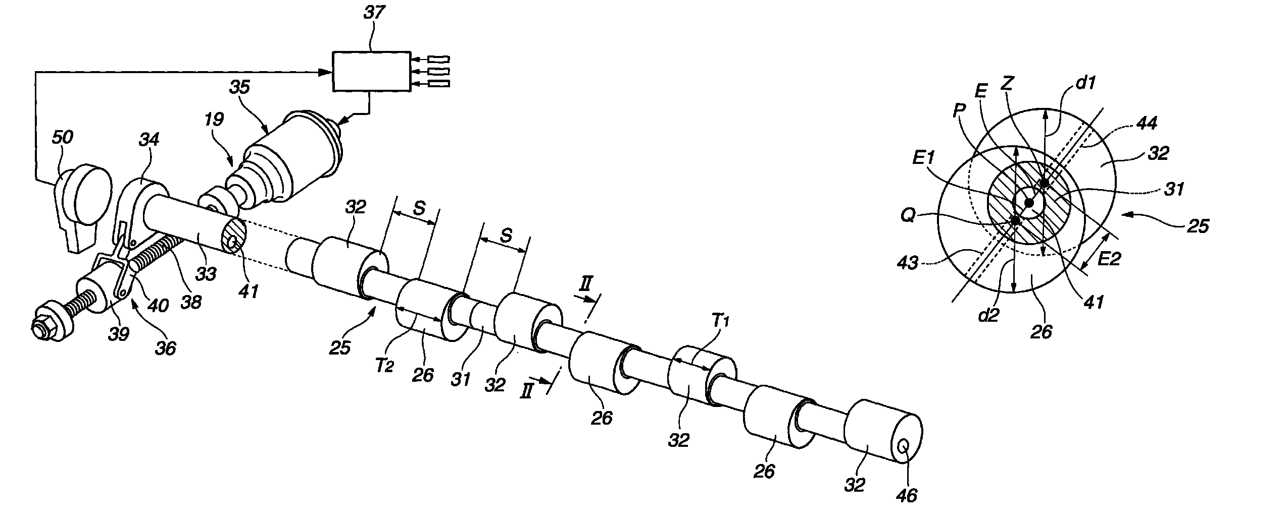
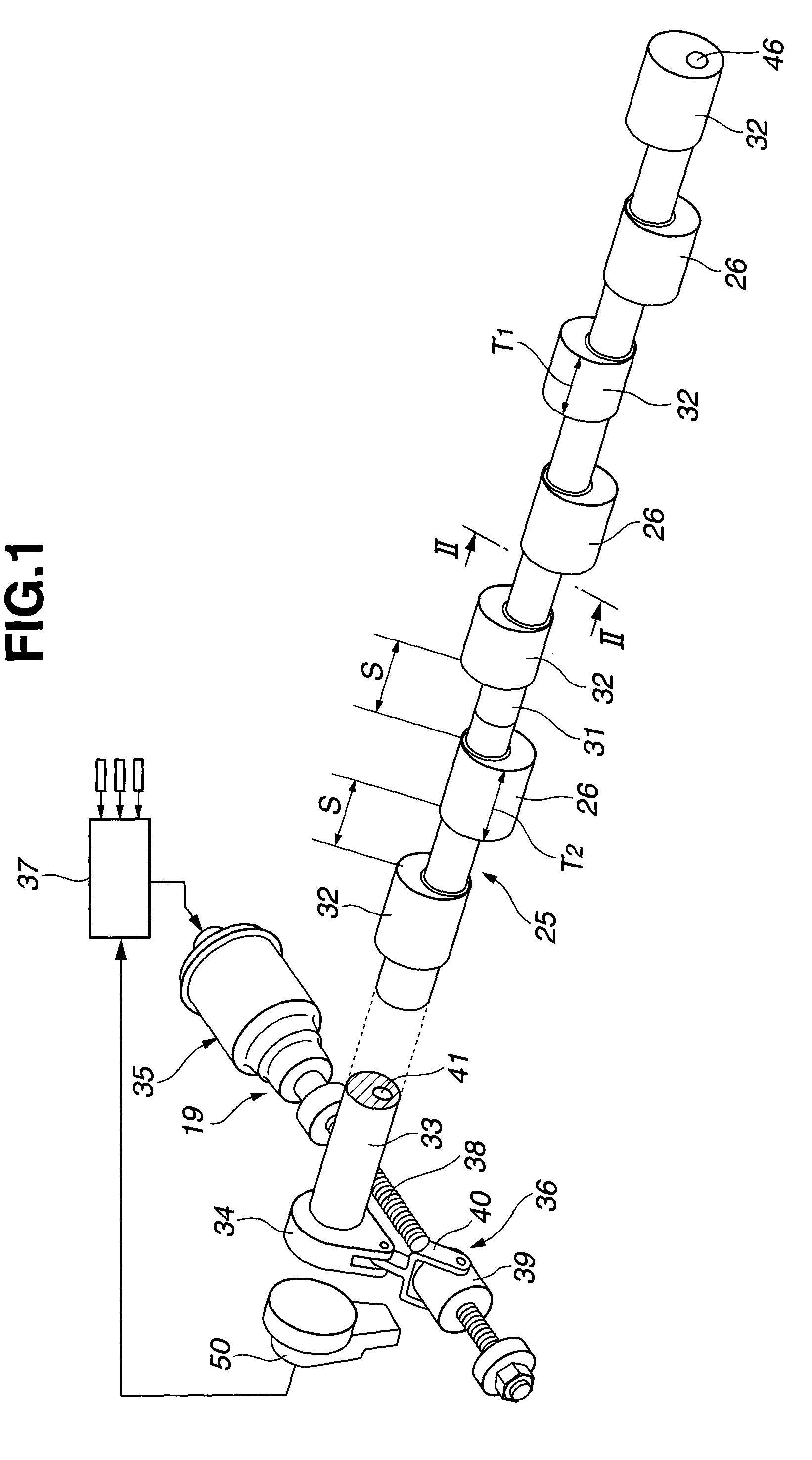
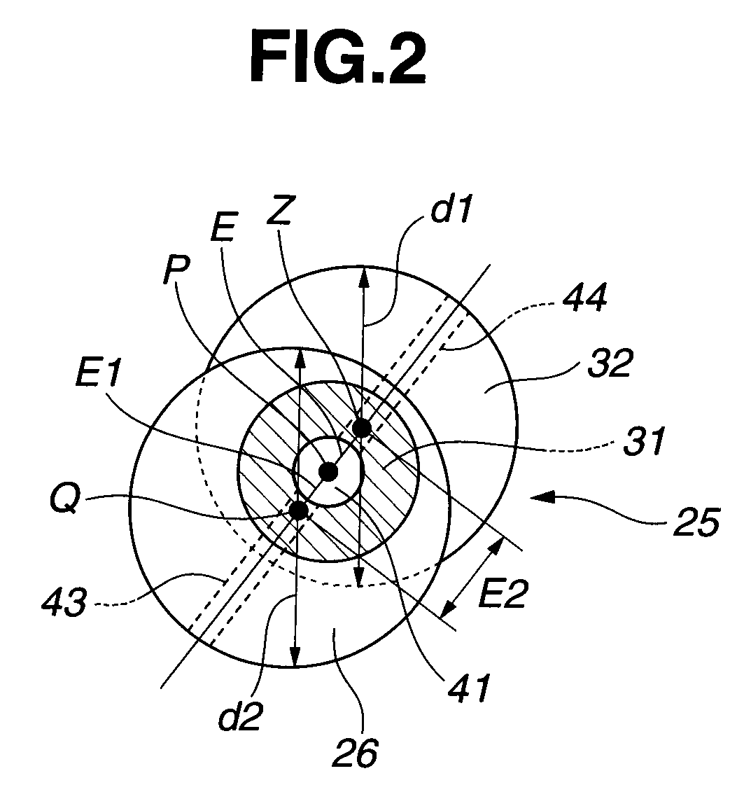
FIG. 1 is a perspective view showing a control shaft and a control cam provided to a variable valve actuating apparatus according to a first embodiment of the present invention. FIG. 2 is a sectional view taken along a section line II-II of FIG. 1. FIG. 3 is a perspective view showing a main part of the variable valve actuating apparatus according to the first embodiment of the present invention. FIG. 4 is a plan view showing the main part of the variable valve actuating apparatus of FIG. 3. FIG. 5 is a front view showing the main part of the variable valve actuating apparatus of FIG. 3. FIG. 6 is a perspective view showing a rocker arm provided to the variable valve actuating apparatus of FIG. 3. FIG. 7 is a longitudinal sectional view showing the variable valve actuating apparatus in which the control shaft is supported by bearings. FIGS. 8A-8D show an assembly process of the rocker arm of the variable valve actuating apparatus. FIG. 9A is an illustrative view showing a close stat...
second embodiment
FIG. 12 is a sectional view taken along a section line II-II of FIG. 1, in a variable valve actuating apparatus according to a second embodiment of the present invention. Journal portion 32 has an outside diameter d1 smaller than an outside diameter d2 of control cam 26. A part of arc of the outer circumferential surface of journal portion 32 corresponds to (coincides with) a part of arc of the outer circumferential surface of shaft portion 31. That is, the part of the outer shape of journal portion 32 substantially corresponds to (coincides with) the part of the outer shape of shaft portion 31.
In the second embodiment, journal portion 32 has small outside diameter d1, and accordingly it is possible to decrease the friction when the entirety of control shaft 25 is rotated. Moreover, journal portion 32 has the outside diameter d1 smaller than inside diameter d of rocker arm support hole 21. As mentioned above, it is possible to further facilitate the mounting operation of rocker arm ...
third embodiment
FIG. 13 is a sectional view taken along a section line II-II of FIG. 1, in a variable valve actuating apparatus according to a third embodiment of the present invention. Journal portion 32 has an outside diameter d1 substantially identical to outside diameter d2 of control cam 26, like the first embodiment. Shaft portion 31 has a sectional shape which is out-of-round, and which is ellipse that is in an area surrounded by a part of the outer circumference of journal portion 32 and a part of the outer circumference of control cam 26.
In this embodiment, the section area is increased, and accordingly it is possible to increase the strength of shaft portion 31, and to improve the freedom of the layout of oil passage 41.
PUM
 Abstract
Description
Claims
Application Information
 - R&D
- Intellectual Property
- Life Sciences
- Materials
- Tech Scout
- Unparalleled Data Quality
- Higher Quality Content
- 60% Fewer Hallucinations
Browse by: Latest US Patents, China's latest patents, Technical Efficacy Thesaurus, Application Domain, Technology Topic, Popular Technical Reports.
© 2025 PatSnap. All rights reserved.Legal|Privacy policy|Modern Slavery Act Transparency Statement|Sitemap|About US| Contact US: help@patsnap.com