Frictionless quick-response balance system

A fast-response, balanced system technology, applied in the direction of fluid pressure actuators, servo motors, mechanical equipment, etc., can solve problems such as insufficient air supply pressure, insufficient air film thickness, and the possibility of damage to lifting devices and machine tools, etc., to achieve guaranteed Safety and reliability, improvement of work performance, effect of reducing reaction force

Inactive Publication Date: 2015-07-29
GUANGDONG UNIV OF TECH
View PDF8 Cites 0 Cited by
  • Summary
  • Abstract
  • Description
  • Claims
  • Application Information

AI Technical Summary

Problems solved by technology

[0002] The existing frictionless quick-response balance system generally uses a single ventilation mechanism to complete the tasks of gas suspension support and lifting load at the same time. The air flow of the orifice in the suspension support part is insufficient, resulting in insufficient thickness of the air film, which affects the effect of air suspension
In addition, the existing frictionless quick-response balancing system adopts a structure in which the load is directly lifted by the piston rod. When the movement axis of the movable component of the frictionless quick-response balancing device is eccentric to the axis of the Y-axis moving up and down of the ultra-precision machine tool, the eccentricity cannot be eliminated. The impact of the force on the balance of the entire lifting device and the Y-axis of the machine tool, as well as the possibility of damaging the lifting device and the machine tool, will affect the stability and reliability of the entire machine tool.

Method used


Image

  • Frictionless quick-response balance system

Examples


Embodiment

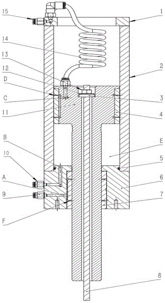
[0012] The structure diagram of the present invention is as figure 1 As shown, the frictionless quick-response balance system of the present invention includes an upper end cover 1, a cylinder body 2, a piston bushing 4, a lower end cover 6, a lower end cover bushing 7, a steel wire rope 8, and a piston rod 11, wherein the piston rod 11 is inserted into In the hollow cavity provided by the cylinder body 2, the piston bushing 4 is sleeved on the outer side of the upper end of the piston rod 11, and the outer side of the piston bushing 4 is in contact with the inner side wall of the cylinder body 2, and the upper and lower ends of the cylinder body 2 are respectively equipped with The upper end cover 1 and the lower end cover 6, the lower end cover shaft sleeve 7 is set on the inner side wall of the lower end cover 6, one end of the piston rod 11 is placed in the hollow cavity provided by the cylinder body 2, and the other end of the piston rod 11 passes through the shaft of the ...


PUM


Abstract

The invention discloses a frictionless quick-response balance system, comprising a cylinder body, a piston shaft sleeve, a lower end cover shaft sleeve, a steel wire rope and a piston rod; the piston rod is inserted into a hollow cavity of the cylinder body; the piston shaft sleeve is installed outside the upper end part of the piston rod in a sleeving manner; the outside of the piston shaft sleeve contacts the inside wall of the cylinder body; an upper end cover and a lower end cover are respectively arranged at the upper and lower end parts of the cylinder body; the lower end cover shaft sleeve is installed on the inside wall of the lower end cover in the sleeving manner; one end of the piston rod is arranged in the hollow cavity of the cylinder body, and the other end of the piston rod passes through the lower end cover shaft sleeve and stretches out from the hollow cavity of the cylinder body; the steel wire rope passes through the hollow cavity of the piston rod; the top part of the steel wire rope is fixed in a groove in the upper part of the piston rod by a nut; the lower part of the steel wire rope passes through the hollow cavity of the piston rod, is exposed outside the piston rod and is used for lifting a load. According to the frictionless quick-response balance system disclosed by the invention, the load can be moved up and down frictionlessly, and the influence on balance of an entire lifting device and a machine tool Y axis due to an eccentric force can be eliminated; therefore, the stability and the reliability of the work are improved.

Description

technical field [0001] The invention is a frictionless quick response balancing system, in particular a lifting balancing device used as a Y-axis up and down movement of an ultra-precision machining machine tool, which belongs to the innovative technology of a frictionless quick response balancing system. Background technique [0002] The existing frictionless quick-response balance system generally uses a single ventilation mechanism to complete the tasks of gas suspension support and lifting load at the same time. The air flow of the orifice in the suspension support part is insufficient, resulting in insufficient thickness of the air film, which affects the effect of air suspension. In addition, the existing frictionless quick-response balancing system adopts a structure in which the load is directly lifted by the piston rod. When the movement axis of the movable component of the frictionless quick-response balancing device is eccentric to the axis of the Y-axis moving u...

Claims


Application Information

Patent Timeline
IPC IPC(8): F15B11/06F15B15/02
CPCF15B11/06F15B15/02
Inventor 刘强王哲李克天陈新陈新度李明泽朱涛周春强王晗王素娟吴佩萱
Owner GUANGDONG UNIV OF TECH
Why Eureka
Try Eureka