Rotary compressor

A technology of rotary compressors and compression chambers, which is applied in the direction of rotary piston machines, rotary piston pumps, rotary piston/swing piston pump components, etc., and can solve the problems that the piston cannot be installed on the eccentric part, etc.

Active Publication Date: 2020-04-17
DAIKIN IND LTD
View PDF5 Cites 0 Cited by
  • Summary
  • Abstract
  • Description
  • Claims
  • Application Information

AI Technical Summary

Problems solved by technology

With such a structure, when the piston is assembled to the eccentric portion while moving the piston in the axial direction of the drive shaft from the main shaft portion and the counter shaft

Method used


Image

  • Rotary compressor
  • Rotary compressor
  • Rotary compressor

Examples


no. 1 approach 》

[0070] A first embodiment of the present invention will be described.

[0071] -The overall structure of the compressor-

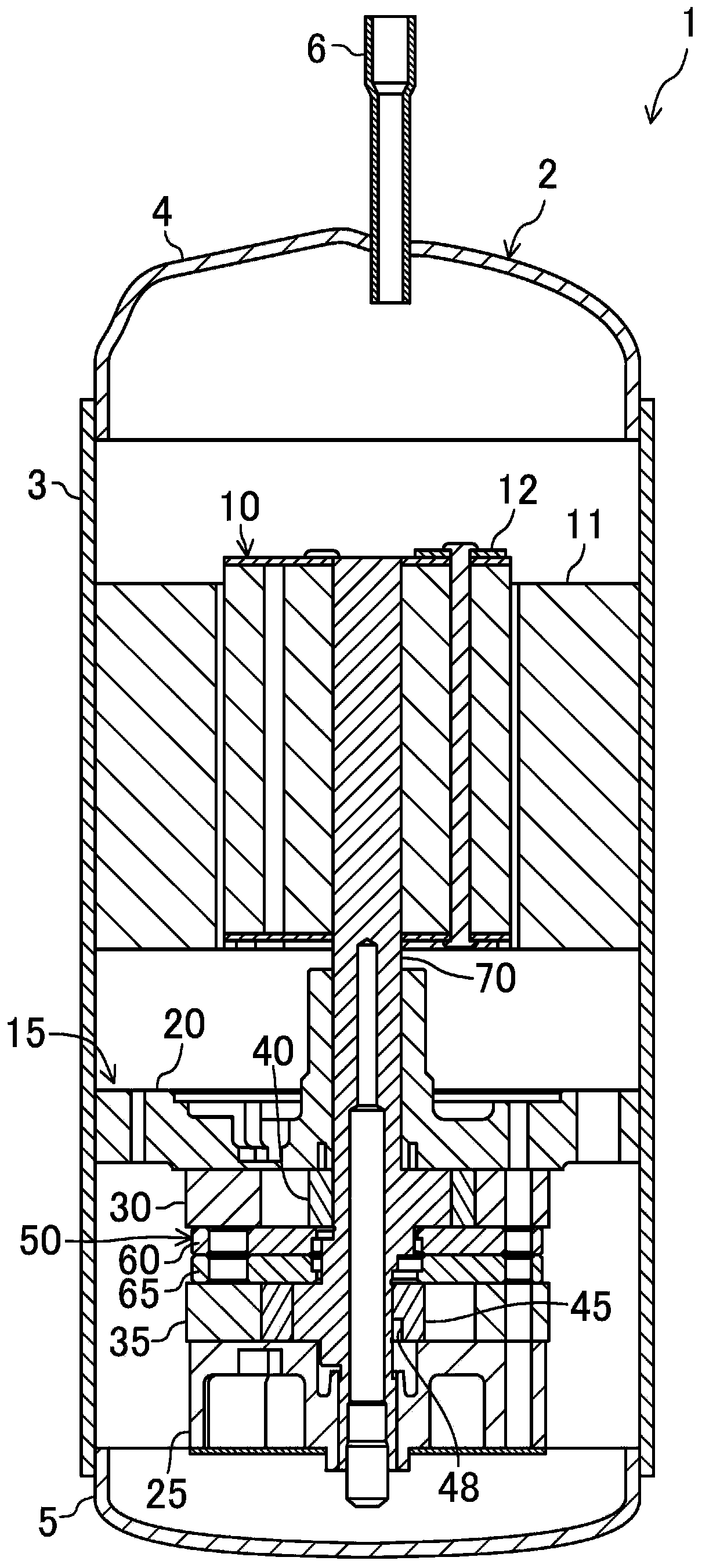
[0072] Such as figure 1 As shown, the compressor of this embodiment is a hermetic rotary compressor 1 . In the rotary compressor 1 , a compression mechanism 15 and a motor 10 are housed in a casing 2 . The rotary compressor 1 is installed in a refrigerant circuit that performs a vapor compression refrigeration cycle, and compresses refrigerant that has been evaporated by an evaporator by sucking it in.

[0073] The casing 2 is a cylindrical airtight container in an upright state. The casing 2 includes a cylindrical body portion 3 and a pair of end plates 4 and 5 that block the ends of the body portion 3 . A suction pipe (not shown) is attached to the lower portion of the trunk portion 3 . A discharge pipe 6 is attached to the upper end plate 4 .

[0074] The electric motor 10 is arranged in an upper portion of the inner space of the housing 2 . The ...

no. 1 approach

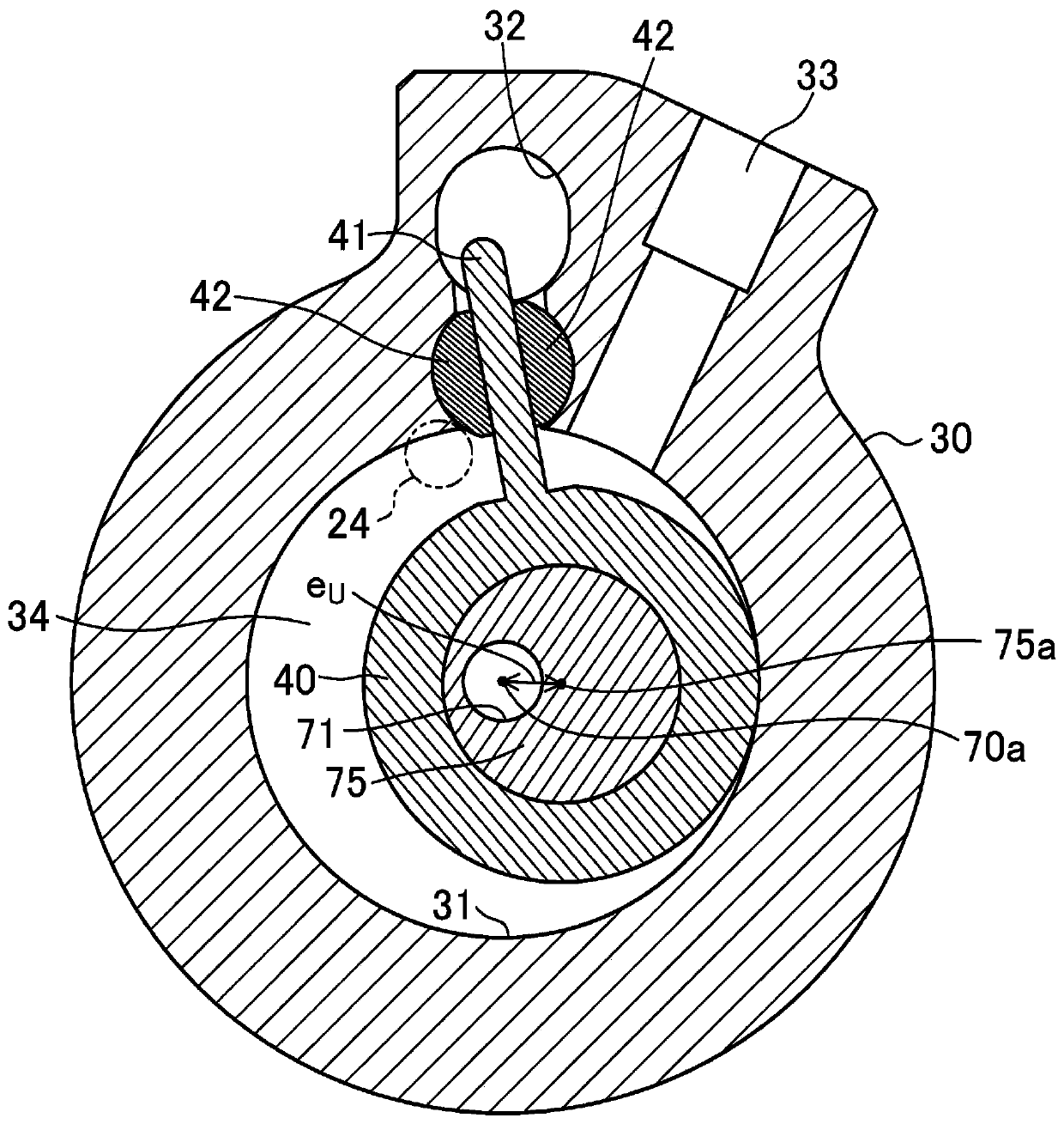
[0196] In addition, in the first embodiment, the drive shaft 70 is configured such that the distance r which is the minimum value of the distance from the rotation center axis 70 a of the drive shaft 70 to the outer peripheral surface of the upper eccentric portion 75 8 The radius R of the spindle portion 72 M Above (r 8 = R eU -e U ≥R M ). That is, the drive shaft 70 is configured such that the outer surface of the drive shaft 70 is not dented toward the eccentric side at the upper eccentric portion 75 . Therefore, when assembling the lower piston 45 and the upper piston 40 to the lower eccentric portion 76 and the upper eccentric portion 75, the drive shaft 70 can be inserted into the lower piston 45 from the counter shaft portion 74 side and can be inserted from the main shaft portion 72 side. The upper piston 40 is inserted and assembled. Accordingly, instead of assembling the upper piston 40 to the upper eccentric portion 75 over the lower eccentric portion 76 , the...

other Embodiment approach

[0198] The above-described embodiments may also take the following configurations.

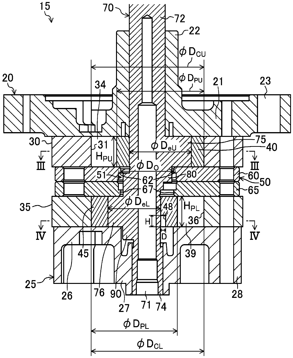
[0199] In the first embodiment described above, the first coupling portion is formed between the counter shaft portion 74 and the lower eccentric portion 76 so that the drive shaft 70 satisfies R eL -e L S , but it may also be configured such that the first connecting portion according to the present invention is formed between the main shaft portion 72 and the upper eccentric portion 75 so that the drive shaft 70 satisfies R eU -e U M .

[0200] Specifically, in the first embodiment described above, the lower cylinder 35 constitutes the first cylinder, the lower piston 45 constitutes the first piston, the lower eccentric portion 76 constitutes the first eccentric portion, and the subshaft portion 74 constitutes the first piston. The upper cylinder 30 constitutes the second cylinder, the upper piston 40 constitutes the second piston, the upper eccentric portion 75 constitutes the second ecc...


PUM


Abstract

In a rotary compressor (1), a lower-side connection part (90) is provided between an auxiliary shaft part (74) and a lower-side eccentric part (76) of a drive shaft (70); the distance obtained by subtracting the amount of eccentricity eL of the lower-side eccentric part (76) from the radius ReL of the lower-side connection part (90) is less than the radius RS of the auxiliary shaft part (74); andthe lower-side connection part (90) is configured such that the height HCL thereof is less than the height HPL of a lower-side piston (45), without the outer surface of the lower-side connection part(90) protruding beyond the outer surface of the lower-side eccentric part (76). A circumferentially extending inner circumferential groove (48) is formed on an end part of the lower-side piston (45) toward the lower-side-connection part (90) on the inner circumferential surface, the inner circumferential groove (48) being provided to avert contact between the auxiliary shaft (74) and the inner circumferential surface of the lower-side piston (45) when the lower-side piston (45) is on the outer circumferential side of the lower-side connection part (90) and the inner circumferential surface ofthe lower-side piston (45) is further outward than the outer circumferential surface of the lower-side eccentric part (76).

Description

technical field [0001] The present invention relates to a rotary compressor which sucks fluid and then compresses it. Background technique [0002] Conventionally, there is known a rotary compressor in which a piston is rotated eccentrically in a cylinder to compress refrigerant. In this type of rotary compressor, there is a case where, by increasing only the amount of eccentricity without increasing the diameter of the eccentric portion of the drive shaft and the height of the cylinder, the sliding loss of the cylinder and the piston is not increased. Increased capacity is sought (for example, refer to the following Patent Document 1). [0003] However, in the above-mentioned rotary compressor, when the diameter of the eccentric portion of the drive shaft is kept constant and the amount of eccentricity is increased, the outer surface of the eccentric portion on the side opposite to the eccentric side, that is, on the reverse eccentric side, is located at a lower position t...

Claims


Application Information

Patent Timeline
IPC IPC(8): F04C18/356F04C18/32F04C23/00F04C29/00
CPCF04C18/32F04C18/356F04C29/0057F04C23/001F04C29/0071F04C2240/60
Inventor 外岛隆造西村公佑东洋文
Owner DAIKIN IND LTD
Why Eureka
Try Eureka