Extendable reaching tool

a technology of extension and tool, which is applied in the direction of hoisting equipment, mechanical control devices, instruments, etc., can solve the problems that the twisting motion may not be particularly useful, and achieve the effect of convenient assembly and low cos

Inactive Publication Date: 2011-11-22
IAMS
View PDF23 Cites 37 Cited by
  • Summary
  • Abstract
  • Description
  • Claims
  • Application Information

AI Technical Summary

Benefits of technology

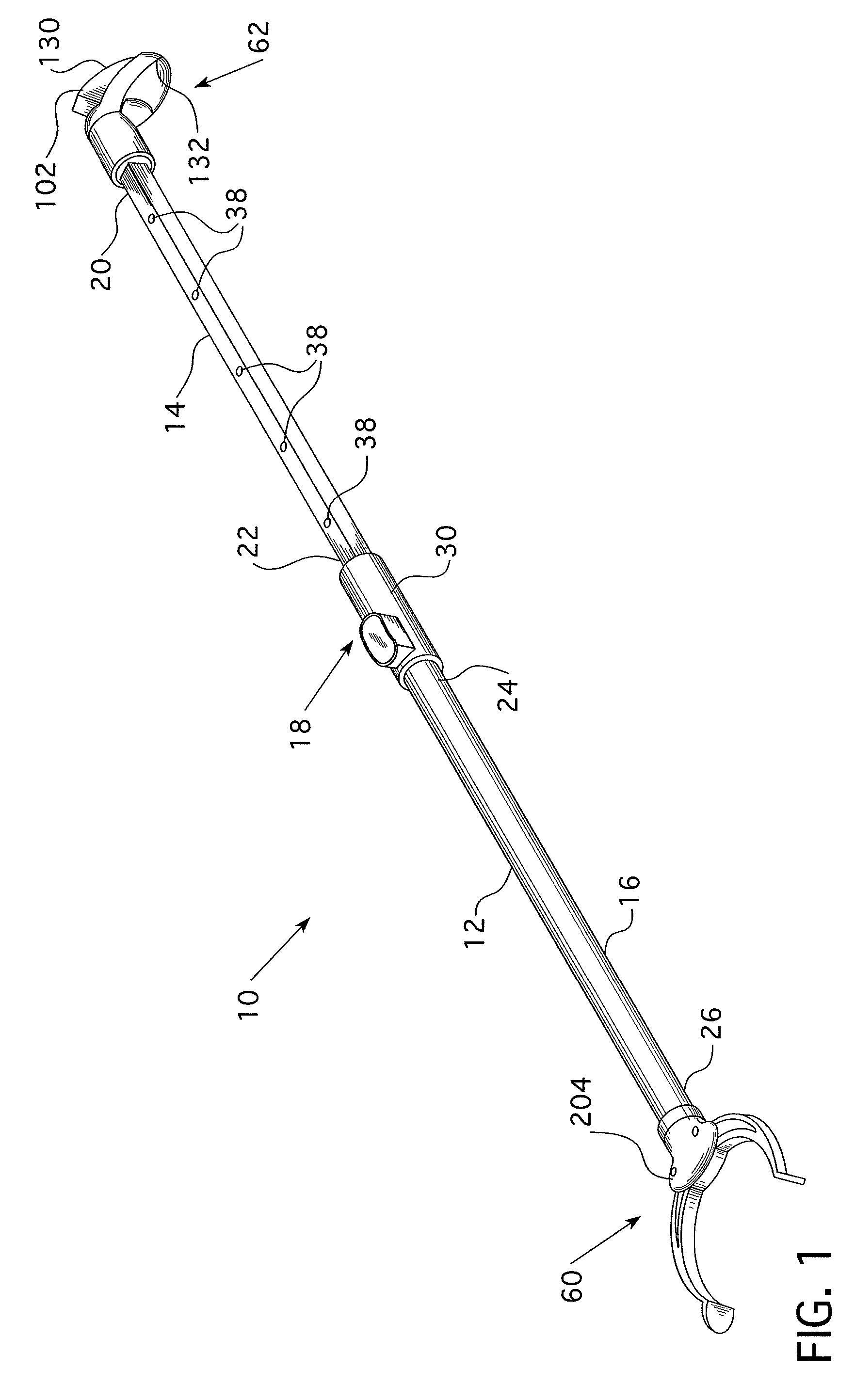
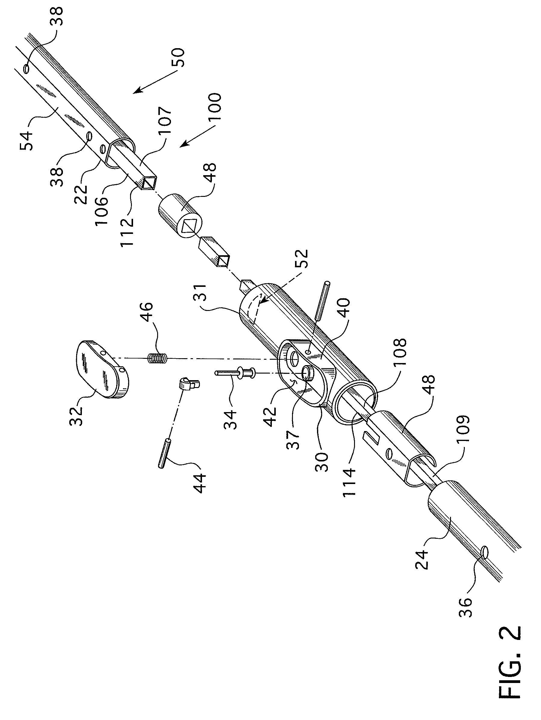
[0008]The disclosed and claimed concept provides for an inexpensive and easy to assemble extendable tool having an internal drive assembly. The extendable components of the internal drive assembly are two, or more, telescoping drive shafts each having an alignment structure. The alignment structure ensures that the drive shafts generally maintain their circumferential alignment relative to each other, i.e. the shafts rotate together and maintain their orientation, while allowing the drive shafts to slide axially relative to each other. In one embodiment the drive shafts have a non-circular cross-section, and more preferably, a square cross-section. Each inner drive shaft has a cross-sectional area that is slightly smaller than the next larger outer drive shaft. Thus, the drive shafts may slide axially relative to each other. However, when the drive shafts are rotated, the non-circular shape causes the inner drive shaft and the next larger outer drive shaft to engage each other and rotate together.

Problems solved by technology

However, when the drive shafts are rotated, the non-circular shape causes the inner drive shaft and the next larger outer drive shaft to engage each other and rotate together.
Further, because a twisting motion may not be particularly useful at the actuatable tool head assembly, the internal drive assembly may include one or more conversion devices that convert rotational motion to / from another type of motion, typically a linear motion.

Method used


Image

  • Extendable reaching tool
  • Extendable reaching tool
  • Extendable reaching tool

Examples


Embodiment Construction

[0020]As used herein, “generally linear,” when used to describe the motion of the handle lever second end, includes an arcuate motion over a small arc. That is, when the radius of the arc is substantially larger than the length of the arc, the motion is “generally linear.”

[0021]As used herein, “coupled” means a link between two or more elements, whether direct or indirect, so long as a link occurs.

[0022]As used herein, “directly coupled” means that two elements are directly in contact with each other.

[0023]As used herein, “fixedly coupled” or “fixed” means that two components are coupled so as to move as one while maintaining a constant orientation relative to each other.

[0024]As used herein, the word “unitary” means a component is created as a single piece or unit. That is, a component that includes pieces that are created separately and then coupled together as a unit is not a “unitary” component or body.

[0025]However, as used herein, a “fixed location” means that two or more elem...


PUM


Abstract

An extendable tool having an internal drive assembly is disclosed. The extendable components of the internal drive assembly are two, or more, telescoping drive shafts each having an alignment structure. The alignment structure ensures that the drive shafts generally maintain their circumferential alignment relative to each other, i.e. the shafts rotate together and maintain their orientation, while allowing the drive shafts to slide axially relative to each other. In one embodiment the drive shafts have a non-circular cross-section, and more preferably, a square cross-section. Each inner drive shaft has a cross-sectional area that is slightly smaller than the next larger outer drive shaft. Thus, the drive shafts may slide axially relative to each other. However, when the drive shafts are rotated, the non-circular shape causes the inner drive shaft and the larger outer drive shaft to engage each other and rotate together.

Description

BACKGROUND OF THE INVENTION[0001]1. Field of the Invention[0002]This invention relates to extendable tools and, more specifically, to an extendable reaching tool.[0003]2. Background Information[0004]Extendable tools are typically used to interact with overhead objects that may be close or remote. For example, a fruit picker may be able to reach fruit on the bottom of a tree by hand, need a short tool for slightly higher fruit, and a longer tool for fruit near the top of the tree. An extendable tool typically includes an extendable shaft having one or more hollow members disposed in a telescoping relationship. Thus, a user may collapse the shaft when working on / with a close object, or, extend the shaft members when working on a remote object. The shaft members are typically maintained in place by a pin passing through at least two shaft members or a compressive collar.[0005]Some extendable tools have fixed tool heads, e.g. a dust mop, or a flexible tool head, e.g. a device for swappi...

Claims


Application Information

Patent Timeline
Patent Type & Authority Patents(United States)
IPC IPC(8): B66F19/00
CPCB25G1/04B25J1/04Y10T74/20396
Inventor HATCHER, STEPHEN D
Owner IAMS
Why Eureka
Try Eureka