
Apparatus for detecting nano particle having nano-gap electrode

a technology of nano-gap electrodes and apparatuses, which is applied in the field of system and method for detecting nano-particles, can solve the problems of affecting human and environmental health, unable quantity of particular nano-particles, and insufficient sensitivity and accuracy to identify the existence/nonexistence of nano-particles. , to achieve the effect of reducing detection time, high reliability and regeneration

Inactive Publication Date: 2011-11-22
KOREA RES INST OF STANDARDS & SCI
View PDF24 Cites 7 Cited by
  • Summary
  • Abstract
  • Description
  • Claims
  • Application Information

AI Technical Summary

Benefits of technology

The present invention relates to a system and method for detecting nanoparticles using a chip-type electronic element with electrodes having a nano-gap. The nanoparticle sensor can identify the presence, concentration, size distribution, and component of nanoparticles with high reliability and regeneration by single measurement. The sensor can be used in various fields such as electronics, handheld machines, and consumer electronics. The detection size limit of nanoparticles is controlled by the size of the nano-gap in the electrodes. The nanoparticle sensor is portable, convenient, and can be used in various environments.

Problems solved by technology

However, the large-scale discharge of engineered nanoparticles into the environment can potentially threaten the human and environmental health, safety problems of the nanoparticles become a pending problem.
The existing particle sensor (Korean Patent Registration No. 10-0315992) is a device of detecting micro scale particle or corpuscles in the air other instead of detecting nano scale particle in all around condition, which does not have a sufficient sensitivity and accuracy to identify the existence / nonexistence and the quantity of the particular nanoparticles.

Method used


Image

  • Apparatus for detecting nano particle having nano-gap electrode
  • Apparatus for detecting nano particle having nano-gap electrode
  • Apparatus for detecting nano particle having nano-gap electrode

Examples


Embodiment Construction

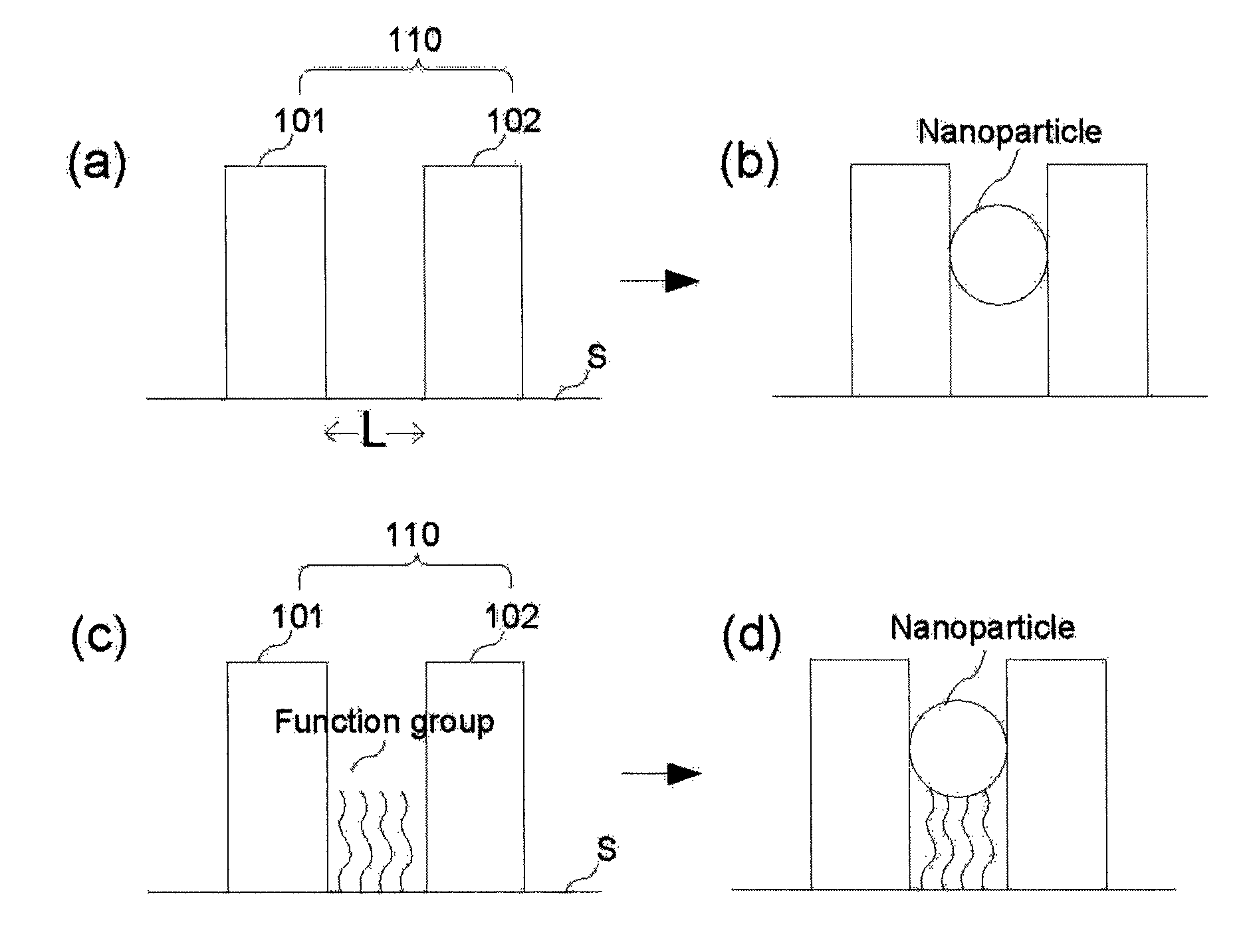
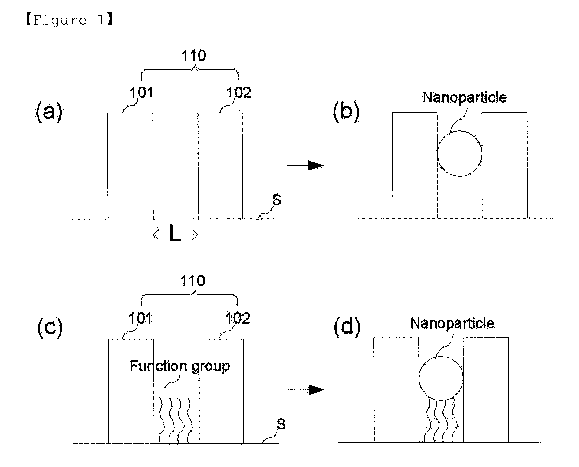
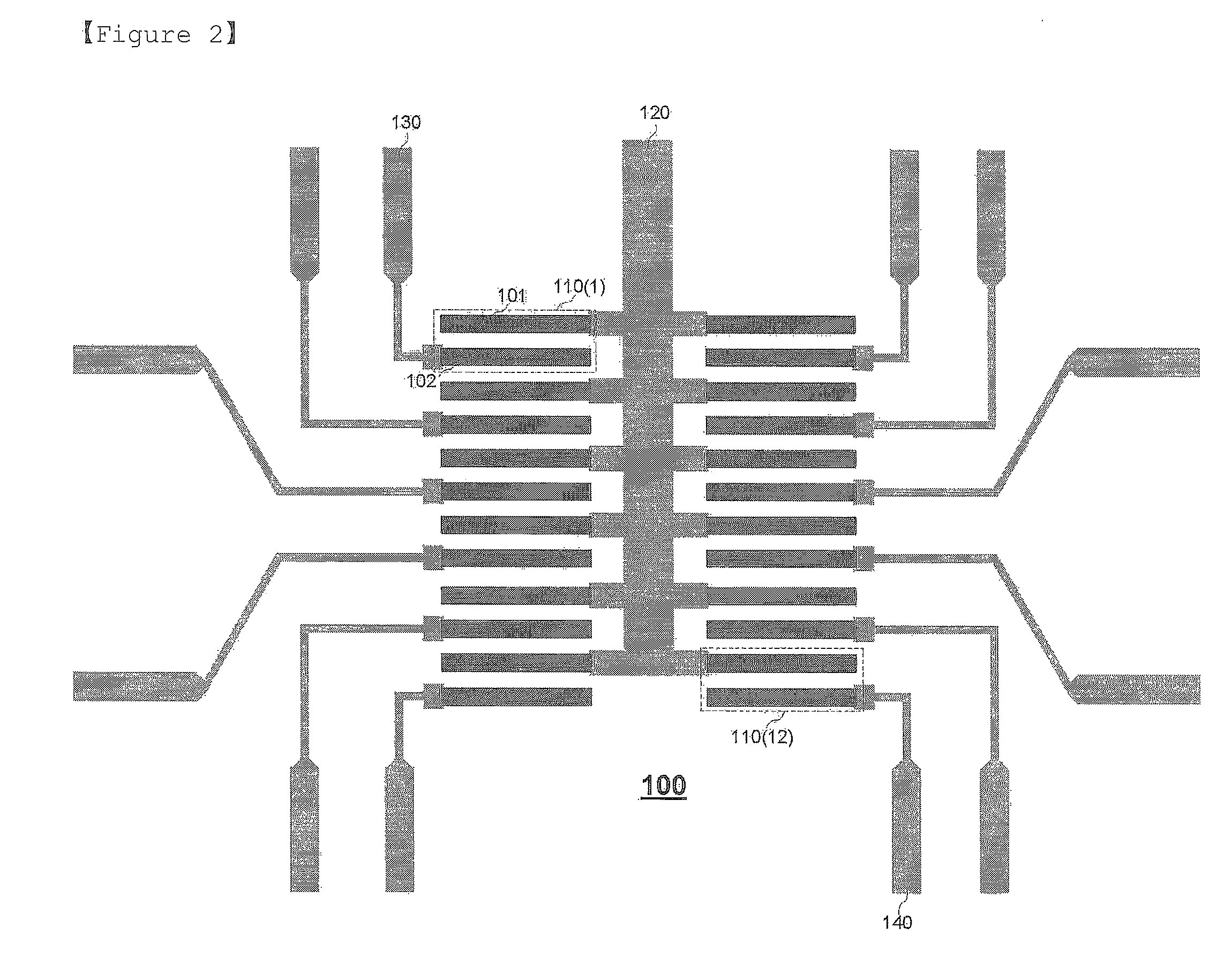
[0030]110: unit electrode[0031]101, 102: electrode pair composing unit electrode[0032]120, 130, 140: metal line

BEST MODE

[0033]Hereinafter, the embodiments of the present invention will be described in detail with reference to accompanying drawings. The accompanying drawings are provided as an example sufficiently to deliver an idea of the present invention to the person skilled in the art. Therefore, the present invention is not bounded by the drawings presented hereinafter but can be specified in another form. Further, like reference numerals denote like element throughout the following detailed description of the invention.

[0034]At this time, if the technological terms and science terms used herein do not have any other definition, they have meanings that can be typically understood by the person skilled in the art. Further, explanations on known functions and structures which can unnecessary make obscure the subject matter of the present invention in the following description and...


PUM

PropertyMeasurementUnit
distanceaaaaaaaaaa
electrical measurementaaaaaaaaaa
sizeaaaaaaaaaa

Abstract

The present invention relates to a nanoparticle sensor which is capable to identify an existence / nonexistence, a concentration, a size distribution and a component of the nanoparticles using an electrode pair having a separated distance of a nano-gap, in which the nanoparticle sensor includes a unit element configured with a plurality of unit electrodes electrically operated independently from each other and detects the nanoparticles based on the number of the unit electrodes electrically changed due to the nanoparticles captured into the nano-gap. The nanoparticle sensor of the present invention can detect the component, the size, the size distribution and the concentration of the nanoparticles by single measurement, have high reliability and regeneration while reducing a detection time by statistical method via a plurality of electrode pairs having the nano-gap, and detect even very low concentration of nanoparticles.

Description

TECHNICAL FIELD[0001]The present invention relates to a system and method for detecting nanoparticles through an electrical device which is capable to identify an existence / nonexistence, a concentration, a size distribution and a component of the nanoparticles using an electrode pair having a separated distance of a nano-gap.BACKGROUND ART[0002]As technologies for synthesis and size control of the nanoparticles are advanced, it has been widely used. Thus new product based on nanotechnology has already appeared on the market and also have been developed. However, the large-scale discharge of engineered nanoparticles into the environment can potentially threaten the human and environmental health, safety problems of the nanoparticles become a pending problem.[0003]Therefore, a demand for technology to identify the existence / nonexistence and a nanoparticle concentration should be increased to solve them. This is becoming important concerns to research an influence which the nanoparticl...

Claims


Application Information

Patent Timeline
Patent Type & Authority Patents(United States)
IPC IPC(8): G01N7/00G01N21/00
CPCG01N27/3278G01N27/00G01N15/00B82Y15/00
Inventor YUN, WAN SOOPARK, HYUNG JULEE, CHO YEON
Owner KOREA RES INST OF STANDARDS & SCI
Learn More