Active improvised explosive device (IED) electronic signature detection

a technology of electronic signature and improvised explosive devices, which is applied in the direction of burglar alarm mechanical actuation, using reradiation, instruments, etc., can solve the problems of amplifying and/or altering the unintentional radiation characteristics of the device, and affecting the operation of the circuit. , to achieve the effect of improving the measuremen

Active Publication Date: 2011-11-22
NOKOMIS
View PDF56 Cites 49 Cited by
  • Summary
  • Abstract
  • Description
  • Claims
  • Application Information

AI Technical Summary

Benefits of technology

[0025]Yet another object of the present invention is to provide a RF emission measurement device that is ne

Problems solved by technology

Emission sources are often susceptible at the same frequencies where they emit.
The introduction of EM field strengths at select frequencies suitable to cause failure, degradation or temporary disruption may amplify and/or alter the unintention

Method used


Image

  • Active improvised explosive device (IED) electronic signature detection
  • Active improvised explosive device (IED) electronic signature detection
  • Active improvised explosive device (IED) electronic signature detection

Examples


Embodiment Construction

, particularly, when such description is taken in conjunction with the attached drawing figures and with the appended claims.

BRIEF DESCRIPTION OF THE DRAWINGS

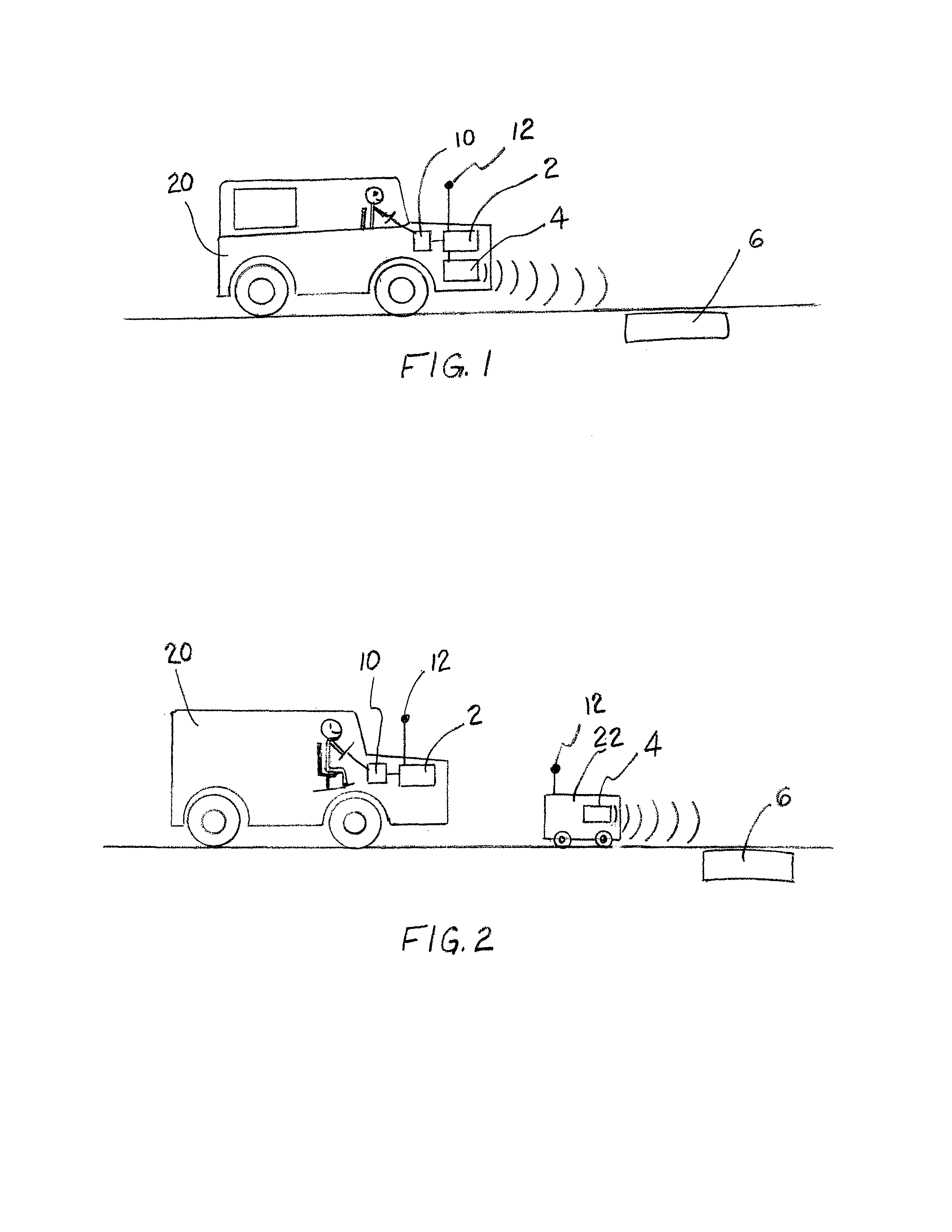
[0029]FIG. 1 is a schematic illustration of one embodiment of the present invention comprising an automobile platform.

[0030]FIG. 2 is a schematic illustration of one embodiment of the present invention comprising an automobile platform and a robotic platform.

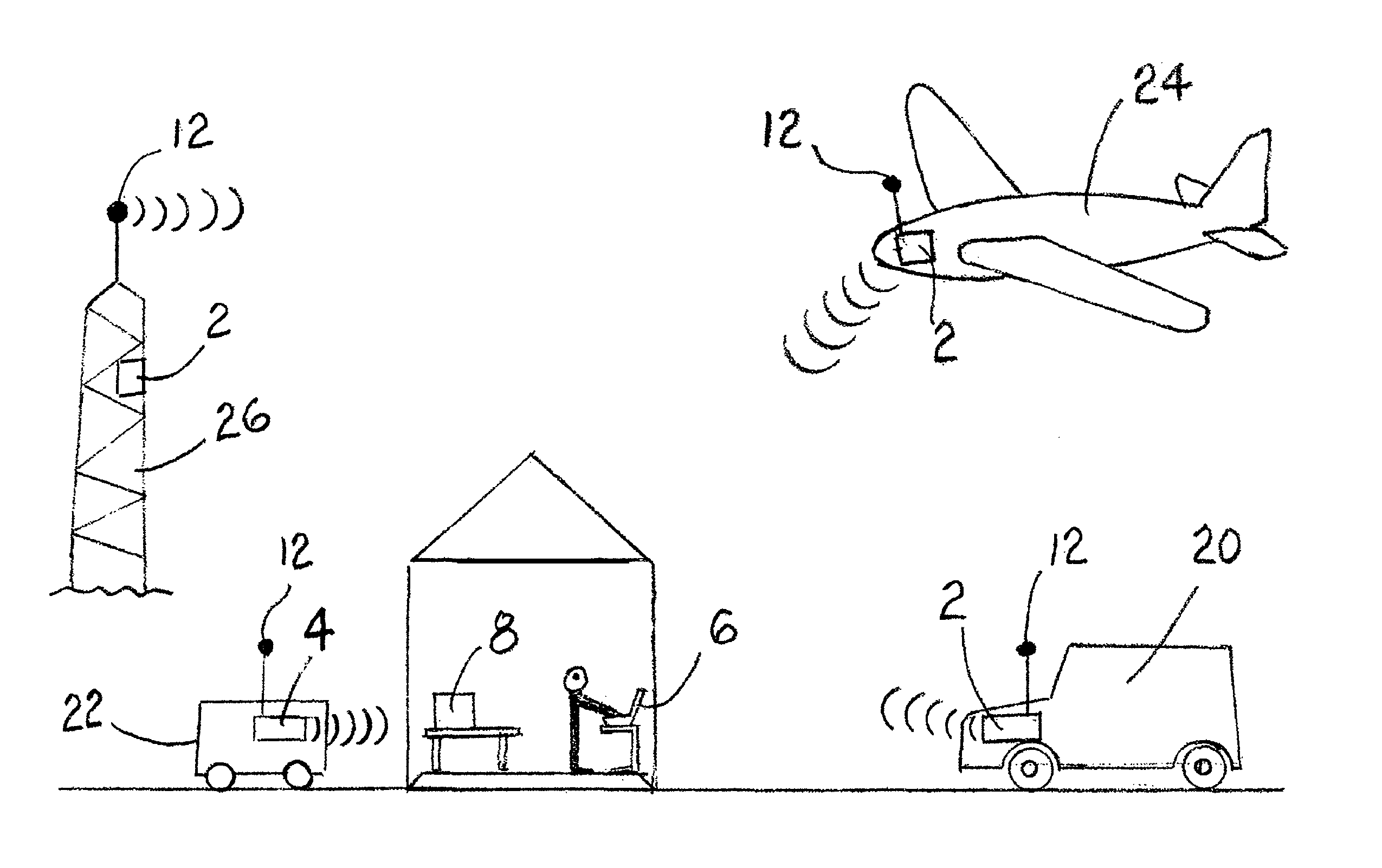
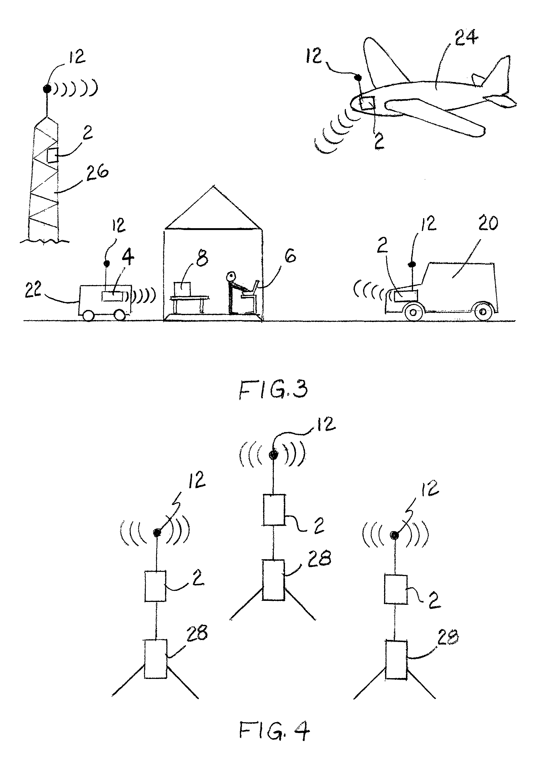
[0031]FIG. 3 is a schematic illustration of one embodiment of the present invention comprising a network of receivers on several platforms.

[0032]FIG. 4 is a schematic illustration of one embodiment of the present invention comprising a network of unattended ground sensors for detecting electronic devices.

BRIEF DESCRIPTION OF A PRESENTLY PREFERRED AND VARIOUS ALTERNATIVE EMBODIMENTS OF THE INVENTION

[0033]Prior to proceeding to the more detailed description of the present invention it should be noted that, for the sake of clarity and understanding, identical components which ...


PUM


Abstract

The present invention provides an apparatus and method of detecting, locating, and suppressing electronic devices, specifically IEDs. This RF emission measurement device in some embodiments can also be considered a system for RF emission measurement, location, and suppression. In some embodiments the apparatus comprises a high sensitivity receiver for receiving and analyzing electronic emissions. In other embodiments the apparatus comprises a high sensitivity receiver and an electromagnetic source for illuminating, and/or suppressing an electromagnetic device. The electromagnetic source could be any electromagnetic emitter known in the art, for example a magnetron or an adjustable wideband electromagnetic emitter.

Description

CROSS REFERENCE TO RELATED APPLICATION[0001]This patent application is related to and claims priority from U.S. Provisional Patent Application Ser. No. 61 / 124,080 filed Apr. 14, 2008 and is herein incorporated by reference.FIELD OF THE INVENTION[0002]The present invention relates, in general, to a method of and an apparatus for significantly enhancing the manner in which electronic devices are located and, more particularly, this invention relates to a method of and an apparatus for significantly enhancing the manner in which improvised explosive devices are located.BACKGROUND OF THE INVENTION[0003]Much of the background of this invention is outlined in U.S. Pat. No. 7,515,094 and is herein incorporated by reference.[0004]It has been demonstrated that there are significant advantages to the analysis of both intentional and unintentional emissions from electronic devices to garner information about the emitting equipment, the information processed by the equipment and the location of...

Claims


Application Information

Patent Timeline
IPC IPC(8): G01S7/42G01S13/00G08B13/14
CPCF41H11/136G01S7/38F41H11/32G01S13/885G01S7/412
Inventor KELLER, WALTER J.
Owner NOKOMIS
Why Eureka
Try Eureka