Antenna operable across multiple frequencies while maintaining substantially uniform beam shape

a technology of antennas and beams, applied in the field of antennas, can solve the problems of changing the beam shape with frequency, complex technologies, and high cos

Active Publication Date: 2011-11-22
BEAS SYST INC
View PDF8 Cites 6 Cited by
  • Summary
  • Abstract
  • Description
  • Claims
  • Application Information

AI Technical Summary

Benefits of technology

[0014]The antenna may further comprise a broad band element arranged to transmit or receive signals from a second field-of-view. The presence of such an element enables the spatial coverage of the antenna to be extended to a complete hemisphere.

Problems solved by technology

This can be difficult, because the electrical size of any antenna aperture changes with frequency, normally resulting in a change of beam shape with frequency: as the frequency increases, the beam becomes narrower.
However, these technologies are complex and expensive.

Method used


Image

  • Antenna operable across multiple frequencies while maintaining substantially uniform beam shape
  • Antenna operable across multiple frequencies while maintaining substantially uniform beam shape
  • Antenna operable across multiple frequencies while maintaining substantially uniform beam shape

Examples


Embodiment Construction

[0018]Further scope of applicability of the present invention will become apparent from the detailed description given hereinafter. However, it should be understood that the detailed description and specific examples, while indicating preferred embodiments of the invention, are given by way of illustration only, since various changes and modifications within the spirit and scope of the invention will become apparent to those skilled in the art from this detailed description.

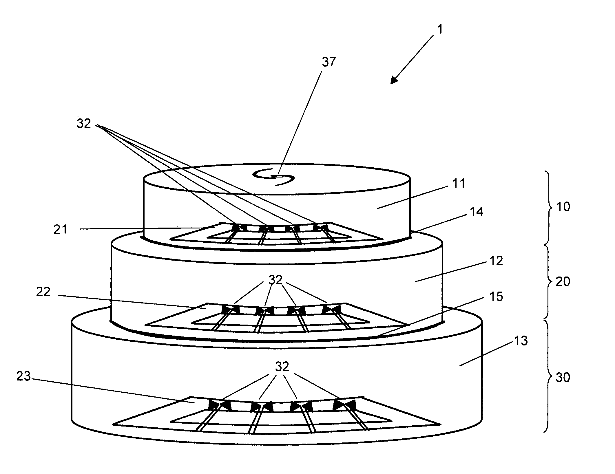
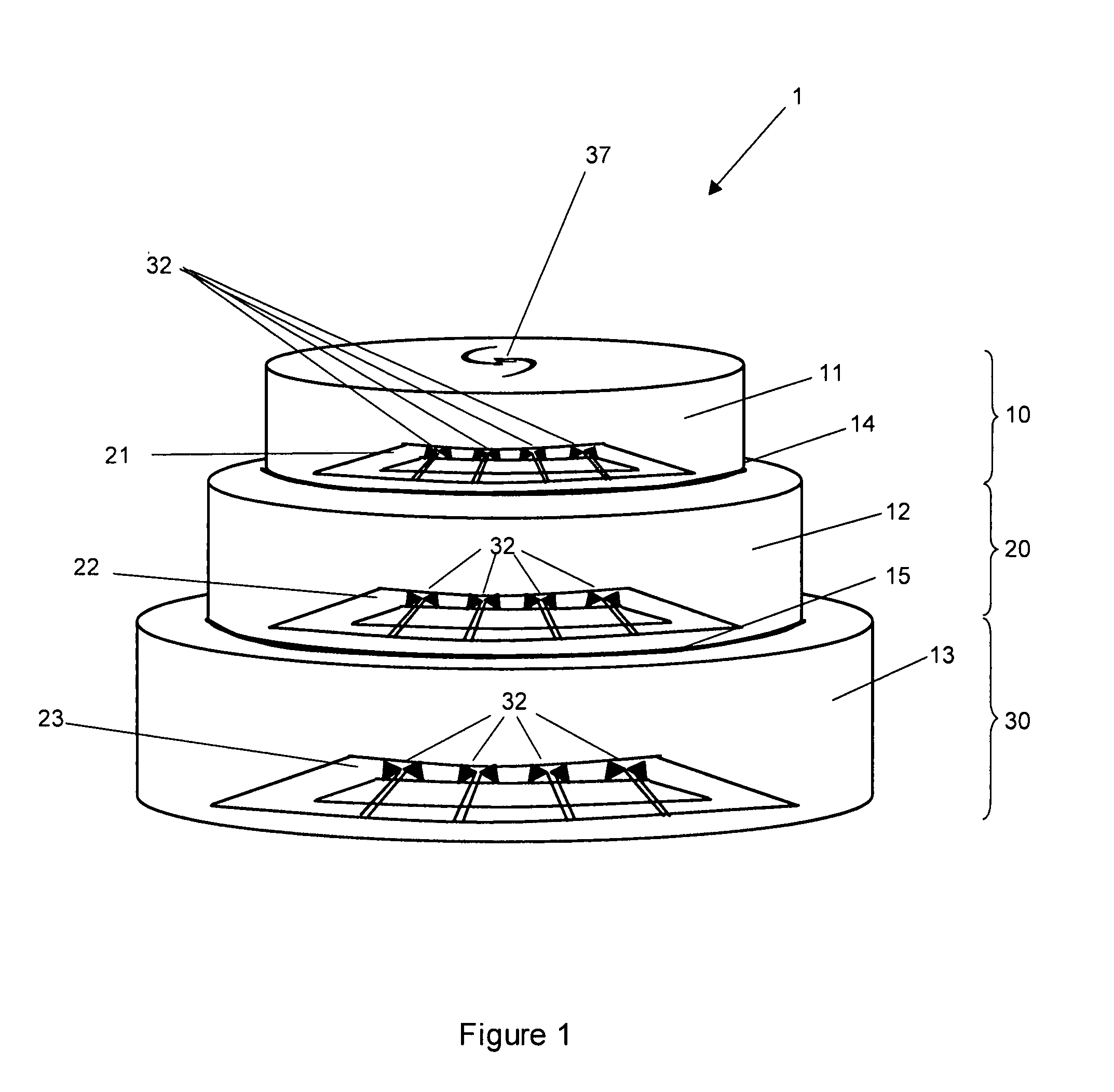
[0019]In FIG. 1 an antenna 1, in accordance with a first embodiment of the invention, comprises three antenna units 10, 20, 30. Each unit comprises a cylindrical lens and an array of beam ports: unit 10 comprises lens 11 and array 21; unit 20 comprises lens 12 and array 22; and unit 30 comprises lens 13 and array 23. Cylindrical lenses 11, 12 and 13 are manufactured from polytetrafluorethylene and are arranged in a coaxial stack. It will be noted that the three cylindrical lenses are of different sizes, lens 11 h...


PUM


Abstract

An antenna including a number of antenna units, each having a lens and an array of beam ports. The antenna units are arranged in a stack, and are configured to transmit or receive signals from the same field-of-view. Each unit is configured to operate in a different frequency band, with the lenses being configured such that an approximately constant beam shape is maintained across the entire operating bandwidth of the antenna.

Description

[0001]This is a national stage of PCT / GB07 / 050241 filed May 8, 2007 and published in English, which has a priority of United Kingdom no. 0609295.1 filed May 11, 2006, and European no. 06270047.1 filed May 11, 2006, hereby incorporated by reference.BACKGROUND OF THE INVENTION[0002]1. Field of the Invention[0003]This invention relates to an antenna, and more particularly to an antenna operable to transmit and receive signals across a range of frequencies whilst maintaining a uniform beam shape.[0004]2. Description of the Related Art[0005]There exist a number of applications in which it is desirable for an antenna to be able to scan across a broad range of frequencies. In some cases, it is further desirable for such antennas to provide broad spatial coverage. In order to be able to scan across a spatially large area, and provide consistency throughout the relevant frequency band, it is necessary for the beamwidth to remain constant throughout the relevant frequency range. This can be d...

Claims


Application Information

Patent Timeline
Patent Type & Authority Patents(United States)
IPC IPC(8): H01Q19/06H01Q5/00H01Q5/42
CPCH01Q3/24H01Q5/00H01Q5/42H01Q21/062H01Q19/06
Inventor MATTHEWS, JAMES CHRISTOPHER GORDONLEWIS, ROBERT ALANRIECKMANN, CHRISTIAN
Owner BEAS SYST INC
Why Eureka
Try Eureka