Liquid crystal optical switch configured to reduce polarization dependent loss

a technology of polarization dependent loss and optical switch, which is applied in the field of optical communication systems and components, can solve the problems of polarization state, increase the likelihood of large polarization dependent loss (pdl), and uneven intensities of each channel, so as to reduce pdl and reduce pdl

Active Publication Date: 2011-11-22
II VI DELAWARE INC
View PDF19 Cites 1 Cited by
  • Summary
  • Abstract
  • Description
  • Claims
  • Application Information

AI Technical Summary

Benefits of technology

One or more embodiments of the present invention provide an optical device having the structure to perform switching and attenuation of an optical beam with reduced PDL. The optical device includes a birefringent displacer and two liquid LC structures. The first LC structure is used to condition s-polarized components of the optical beam and the second LC structure is used to condition p-polarized components of the optical beam. Each LC structure has a separate control electrode so that the s-polarized components of the optical beam and the p-polarized components of the optical beam can be conditioned differently and in such a manner that reduces PDL. The optical device may also be configured as a wavelength selective switch for processing multiple input light beams, such as the multiple wavelength channels de-multiplexed from a wavelength division multiplexed optical signal.
An optical device according to another embodiment of the present invention is configured to reduce polarization dependent losses by independently controlling p-polarized light components and s-polarized light components. The optical device includes a first LC structure for conditioning the polarization state of incident light and disposed in optical paths of p-polarized components of an input beam and output beams produced from the input beam, the first LC structure having a plurality of LC cells and a first control electrode that applies the same control signal to the LC cells of the first LC structure, and a second LC structure for conditioning the polarization state of incident light and disposed in optical paths of s-polarized components of the input beam and the output beams, the second LC structure having a plurality of LC cells and a second control electrode that applies the same control signal to the LC cells of the second LC structure. The control signal applied by the first control electrode is different from the control signal applied by the second control electrode.

Problems solved by technology

In practice, different wavelength channels of a WDM signal typically undergo asymmetrical losses as they travel through an optical communication system, resulting in unequal intensities for each channel.
Liquid crystal (LC) based optical switches are known in the art for switching and attenuation of the channels contained in a WDM signal, and in some applications offer significant advantages over other optical switch designs, but there is one drawback related to the polarization state of an input light beam.
However, such an approach requires the optical signal to be in the form of two parallel beams, sometimes over a long path length, which increases the likelihood of large polarization dependent losses (PDL) that degrade signal quality.
In addition, because a relatively large optical assembly is needed to perform the polarization walk-off as the optical signal exits the fiber, an undesirably large spacing between the input and output ports of the optical switch, e.g., greater than 1 mm, results.
The use of one optical device to perform switching and another device to perform attenuation in an optical communication system increases the size and complexity of the system, makes erosion of signal quality more likely due to misalignment of the optical devices, and requires a first independent control signal to complete the switching function and a second independent control signal to complete the attenuation function.

Method used


Image

  • Liquid crystal optical switch configured to reduce polarization dependent loss
  • Liquid crystal optical switch configured to reduce polarization dependent loss
  • Liquid crystal optical switch configured to reduce polarization dependent loss

Examples


Embodiment Construction

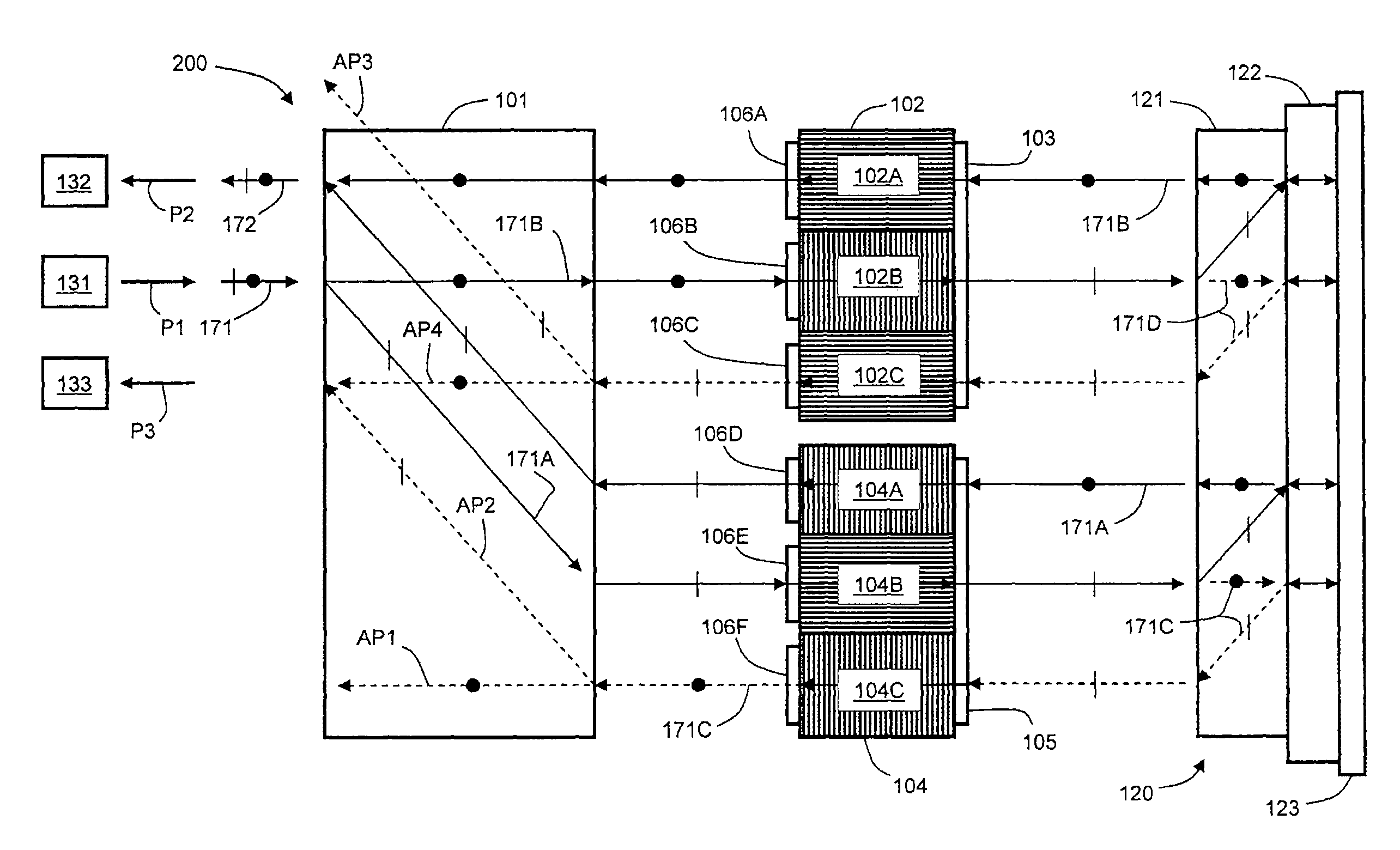
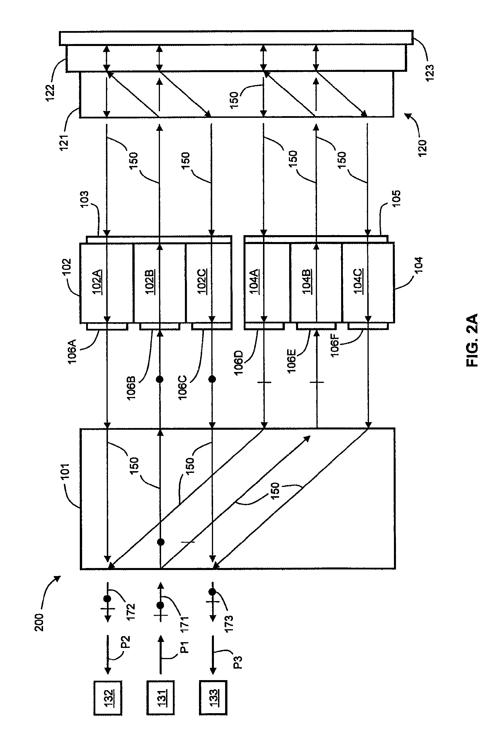
Embodiments of the invention contemplate an optical switching device that performs both 1×2 switching and attenuation of an optical beam with reduced polarization dependent loss (PDL), where the optical beam has an arbitrary combination of s- and p-polarized light. The optical switching device separates the optical beam into s- and p-polarized components and uses a first liquid crystal (LC) beam-polarizing structure and a first control signal for switching and attenuation of the s-component, and a second LC beam-polarizing structure and a second control signal for switching and attenuation of the p-component, so that each polarization component is attenuated by substantially the same amount.

The optical device includes a birefringent displacer, two liquid crystal (LC) beam-polarizing structures having three subpixels each, and a polarization separating and rotating assembly. The birefringent displacer separates input light beams into s- and p-polarized components before the component...


PUM

PropertyMeasurementUnit
optical pathaaaaaaaaaa
birefringentaaaaaaaaaa
wavelengthaaaaaaaaaa

Abstract

An optical device has the structure to perform switching and attenuation of an optical beam with reduced polarization dependent loss (PDL). The optical device includes a birefringent displacer and two liquid crystal (LC) structures. The first LC structure is used to condition s-polarized components of the optical beam and the second LC structure is used to condition p-polarized components of the optical beam. Each LC structure has a separate control electrode so that the s-polarized components of the optical beam and the p-polarized components of the optical beam can be conditioned differently and in such a manner that reduces PDL. The optical device may be configured for processing multiple input light beams, such as the multiple wavelength channels de-multiplexed from a wavelength division multiplexed (WDM) optical signal.

Description

BACKGROUND OF THE INVENTION1. Field of the InventionEmbodiments of the present invention relate generally to optical communication systems and components and, more particularly, to a liquid crystal-based optical switch and attenuator.2. Description of the Related ArtIn optical communication systems, it is sometimes necessary to perform 1×2 switching of an optical signal, where an input light beam enters an optical switching device through an input port and is directed to one of two output ports. There are also more complicated optical switching schemes, such as 2×2, 1×N, and N×N optical switches, which may be realized by combining multiple 1×2 optical switches.In addition to routing of signals by optical switches, attenuation of signals in optical communication systems is needed, for example in an optical communication system that employs wavelength division multiplexing (WDM). In such an optical system, information is carried by multiple channels, each channel having a unique wavel...

Claims


Application Information

Patent Timeline
Patent Type & Authority Patents(United States)
IPC IPC(8): G02B6/35G02F1/13
CPCG02B6/3524G02F1/31G02F1/1396G02F2203/58G02F2203/06
Inventor YUE, XUEFENGLIN, CHRISTOPHERSUN, RUIPENGWANG, RUIBO
Owner II VI DELAWARE INC
Why Eureka
Try Eureka