Y-branch-based thermo-optic digital optical switches and variable optical attenuators with non-uniform heating

a digital optical switch and variable optical technology, applied in the field of optical communication technology, can solve the problems of limiting the applicability of integrated optical circuits, difficult control of such devices, and easy error prone manufacturing

Inactive Publication Date: 2006-07-13
EI DU PONT DE NEMOURS & CO
View PDF1 Cites 2 Cited by
  • Summary
  • Abstract
  • Description
  • Claims
  • Application Information

AI Technical Summary

Benefits of technology

[0036] A further benefit of the present invention is that because the heated length can be shorter, the vertex angle can be as large as 10-15°, ca. 10 times the angles taught in the art. Actual practice in fabricating Y-branches according to the teachings of the art normally results in the creation of un-etched material at the vertex, which greatly aggravates PDL in the propagated signal. As emphasized in Mossburger et al, op.cit., having a “perfect” vertex is critical to performance. With the larger vertex angles of the present invention, it is much easier to achieve sharp definition of the vertex and control of the shape with concomitant reduction in PDL.
[0037] One particularly surprising aspect of the present invention is that contrary to the teachings of Moosburger, a blunted vertex such as that depicted in FIG. 1c can result in reduced PDL with no significant light loss.
[0038] One of skill in the art will appreciate that the heating profile of choice will depend upon many factors including the specific choice of materials from which the waveguide is fabricated, the architecture of the waveguide, whether or not there is an intervening layer of cladding between heater and core, the wavelength of the propagating signal, the rapidity of switching desired, whether or not it is desired to employ the device partly or exclusively as a variable optical attenuator, and so forth.
[0039] It is desirable in the practice of the invention that the heating profile be a smoothly varying function of position on the surface of the waveguide being heated. Sharp discontinuities in heat flux must be avoided in order to avoid sudden changes in refractive index in the waveguide, which can result in mode matching losses.
[0040] In the practice of the present invention it has been found that power levels of 10 to 50 mW are effective in causing switching in polymers characterized by dn / dT in the range of −2 to −5×10⁻⁴ / ° C. Examples of such polymers include but are not limited to polyacrylates, polyfluoroacrylates, and polychloroacrylates. Power levels of 30-150 mW are found to be effective with polymers characterized by dn / dT of −0.5 to less than −2×10⁻⁴ / ° C in absolute value. Examples of such polymers include but are not limited to polycarbonate and polymethylmethacrylate. In a typical embodiment of the present invention, the entire waveguide is made from the same polymeric system.
[0041] In the practice of the present invention, temperature increases in the core may range from 10 to 100° C. The high temperatures are generally narrowly localized, and are beneficially achieved by use of a heater having a relatively narrow “neck” area. As will be understood by one of skill in the art, resistance in a metallic conductor increases inversely with cross-sectional area.
[0042] The present invention is operable with any convenient heating means such as is known in the art. This can include induction heating, radiative heating, and electrical resistive heating. From the standpoint of simplicity of implementation, electrical resistive heating is preferred. Electrical resistive heating may be accomplished according to means wellknown in the art. In one approach, a thin metal strip is sputter coated onto the waveguide using a mask to prepare the heater shape desired. When the heater is not disposed on the surface of the output branch over its entire length, it is deposited on top of that part of the overclad on the chip where there is no core underneath.
[0043] Alternatively, the heater may be formed by evaporation or any other metal deposition process.
[0044] Suitable metals for electrical resistive heating according to the present invention include but are not limited to chromium, titanium, aluminum, nickel, gold, platinum. Preferred are chromium, titanium, nickel, and gold. The spatially non-uniform heating according to the present invention may be accomplished by applying a thin film heating strip of variable cross-sectional area onto the waveguide surface at any convenient location thereupon
[0045] The present invention places no specific limits on the manner in which spatially non-uniform heating may be accomplished. In one embodiment of the present invention, spatially non-uniform heating is beneficially accomplished by employing a heating means of uniform design which is disposed with respect to the waveguide in a manner which results in the imposition of a non-uniform heat flux onto the waveguide surface. Illustrative of this embodiment are the configurations shown in FIG. 4. One of skill in the art will appreciate that many other embodiments of the same generic nature. Such embodiments include but are not limited to rectangular heaters with curved waveguides, rectangular heaters with straight waveguides, curved heaters with straight waveguides, and curved or rectangular heaters with straight waveguides wherein the vertex of said Y-branch is blunted.
[0046]FIG. 4 depicts an embodiment of the invention wherein the output waveguide is curved, the heater is uniform in design, and the heat-flux delivered to the waveguide surface is a smoothly continuous function of the proximity of the heater to the waveguide surface. In this case, the greatest amount of heating occurs at the point farthest from the vertex. Two slightly different embodiments are depicted, differing by the slightly different shapes of the heaters.
[0047] One of skill in the art will appreciate that any of the Y-branch designs depicted in FIGS. 1a-1c, and the others as described hereinabove, can be substituted for the Y-branch depicted in FIGS. 4a and 4b with no loss of effectiveness in the practice of the present invention.
[0048] In a preferred embodiment of the present invention, a heater wherein the cross-sectional area thereof is not constant is disposed along the length of the output waveguides. In this embodiment, a non-uniform heat flux is imposed upon the waveguide surface by virtue of the higher temperatures realized in the portions of the heater having smaller cross-sectional areas. In a more preferred embodiment, the heater is in the shape of a bow-tie wherein a rectangular portion gives way at each end in the longer dimension to a triangular portion, the two triangular portions being joined at their truncated apexes. In this embodiment, the heat flux incident upon the surface of the waveguide increases continuously along the long dimension of the heater as the cross-sectional area narrows until it reaches a peak at the narrowest point, and then continuously decreases with increasing distance from the narrowest point along the long dimension of the waveguide. In the most preferred embodiment hereof, the narrowest portion of the heater is disposed in close proximity to the vertex, thereby subjecting the region of the vertex to the highest temperature. Because of the continuous nature of the effect herein realized, one of skill in the art will understand that a small positional deviation of the narrowest point on the heater from the closest point of approach to the vertex will have little effect on the practive of the present invention.
[0049] The most preferred embodiment is depicted in FIGS. 5a and 5b wherein two slightly different bow-tie designs are placed along the straight output waveguides wherein the Y-branch depicted is that in FIG. 1c wherein the angle β is 0.2-4.0° preferably 0.4-1.0°.
[0051] One of skill in the art will further appreciate that the requisite heating profile of the invention may be obtained by employing a plurality of individually uniform heaters along the length of the output branch, at least two of said heaters being heated to different temperatures. This embodiment is however less preferred because of the multiplicity of wires and controllers which would be required for its implementation.
[0051] One of skill in the art will further appreciate that the requisite heating profile of the invention may be obtained by employing a plurality of individually uniform heaters along the length of the output branch, at least two of said heaters being heated to different temperatures. This embodiment is however less preferred because of the multiplicity of wires and controllers which would be required for its implementation.
[0052] Placement of the heaters according to the present invention may have a significant impact on the operability of the present invention. If a heater is positioned on the top surface of an output branch, it will be in very close proximity to the other output branch, and it is highly likely that some undesirable degree of heating will occur in that output branch which is not intended to be heated. For this reason it is highly desirable that the heat flux from the heaters be directed to the outside edge of the respective branches in order to place as much as possible of the thermally insulating waveguide between the heated surface and the adjacent waveguide. Thus lateral positioning of the heater is an important consideration.
[0053] The Y-branch of the invention may be beneficially employed not only as a digital optical spatial switch but as a variable optical attenuator (VOA). This is accomplished by heating the output branches to temperatures below the threshold temperature for switching. In the operation of the VOA according to the present invention, the degree of transfer of power from one branch to the other is continuously varied by continuously varying the heat input until the stage at which essentially all the optical power is transferred to one output waveguide, after which further heating has no effect—the digital switching region. When the Y-branch is operated as a VOA, a first arm is heated to achieve attenuation up to 3 dB or 50% (in polymer, said first arm is not the output arm), and the second arm is heated to achieve attenuation above 3 dB (in polymer, said second arm is the output arm). The heat may then be subject to small adjustments to alter the relative intensity of propagation in the two branches.

Problems solved by technology

One persistent problem presented to the designer by the Y-branches of the art is footprint.
Controlled fabrication of such devices is quite difficult and error prone.
Furthermore, the large footprint of such devices greatly limits their applicability in integrated optical circuitry.

Method used


Image

  • Y-branch-based thermo-optic digital optical switches and variable optical attenuators with non-uniform heating
  • Y-branch-based thermo-optic digital optical switches and variable optical attenuators with non-uniform heating
  • Y-branch-based thermo-optic digital optical switches and variable optical attenuators with non-uniform heating

Examples


example 1

[0054] In this Example, the following terms are employed:

[0055] The composition designated B3 was prepared by combining 94% by weight of ethoxylated perfluoropolyether diacrylate (MW1100), 4% by weight of di-trimethylolpropane tetraacrylate, and 2% by weight of Darocur 1173, a photoinitiator available from Ciba-Geigy.

[0056] The composition designated BF3 was prepared by combining 98% by weight of ethoxylated perfluoropolyether diacrylate (MW1100) and 2% by weight of Darocur 1173.

[0057] The composition designated C3 was prepared by combining 91% by weight of ethoxylated perfluoropolyether diacrylate (MW1100), 6.5% by weight of di-trimethylolpropane tetra-acrylate, 2% by weight of Darocur1173, and 0.5% by weight of Darocur 4265 a different photoinitiator available from Ciba Geigy.

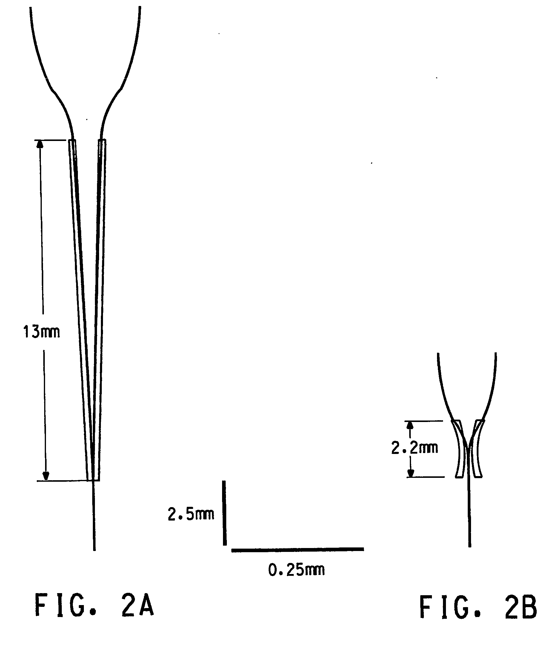
[0058] The following fabrication process was performed twice, once with mask designated P03, once with mask designated P05 (see FIG. 2 for structures of each mask).

[0059] A 6-inch oxidized silicon wafer ...

example 2

[0062] A second Y-branch specimen, prepared in a manner identical to that in Example 1, was evaluated according to the following protocol: The measurement was done in 2 steps:

[0063] 1. 1.55 micrometer wavelength light was coupled from a glass optical fiber input into the Y-branch trunk and after traversing the device the light was couple to a glass optical fiber at the output of the ‘right’ branch and was sent to a photodetector. Electrical power was applied to the left branch heater and was changed continuously from 50 mW to 0 mW, then electrical power was applied to the right heater and was changed continuously from 0 mW to 50 mW. The optical power attenuation measured at the photodetector is indicated by the blue line in FIG. 6.

[0064] 2. Light was launched as in the preceding paragraph. but was coupled to a photodetector at the output of the ‘left’ branch Electrical power was applied to the right heater and was changed continuously from 50 mW to 0 mW, then electrical power was ...


PUM

PropertyMeasurementUnit
angleaaaaaaaaaa
angleaaaaaaaaaa
distanceaaaaaaaaaa

Abstract

The present invention is concerned with 1×2 thermo-optic digital optical switches known in the art as “Y-branch digital optical switches” and variable optical attenuators.

Description

FIELD OF THE INVENTION [0001] The present invention is concerned with optical communications technology. More specifically, the present invention is concerned with 1×2 thermo-optic digital optical switches known in the art as “Y-branch digital optical switches” and variable optical attenuators. TECHNICAL BACKGROUND [0002] Digital optical spatial switches (DOS) are well known in the art. One class of such switches is the 1×2 digital optical switch known as a “Y-branch digital optical switch” (Y-branch DOS) wherein light input into the “base” or trunk of the Y is directed through one or the other of the output branches by virtue of changes effected in the refractive index of one or both of the output branches. The switch can also be operated in reverse, whereby one or the other “upper branches” of the Y can be selected as an input channel with the base of the Y being the output channel. Y-branches are a fundamental building block of optical circuitry, and may be employed singly, or in...

Claims


Application Information

Patent Timeline
Patent Type & Authority Applications(United States)
IPC IPC(8): G02B6/26G02F1/295G02B6/42G02F1/01G02F1/313
CPCG02B6/125G02F1/0147G02F1/3137G02F2201/122G02F2202/022G02F2203/48G02B6/26G02B6/42
Inventor ELDADA, LOUAY
Owner EI DU PONT DE NEMOURS & CO
Why Eureka
Try Eureka