High resolution tunable optical filter

a tunable, optical filter technology, applied in the field of optical devices, can solve the problems of increasing the cost and size of the device, complicating optical alignment, and displaying significant polarization dependent loss (pdl) filter types, and achieve the effect of convenient reduction and increased resolution

Inactive Publication Date: 2006-01-03
LUMENTUM OPERATIONS LLC
View PDF16 Cites 6 Cited by
  • Summary
  • Abstract
  • Description
  • Claims
  • Application Information

AI Technical Summary

Benefits of technology

[0009]The instant invention relates to a high-resolution tunable optical filter that uses a dispersive element in a double pass configuration. The double pass configuration is provided by a reflective quarter-wave plate that conveniently reduces PDL. Advantageously, the filter is tuned by rotating the reflective quarter-wave plate, thus providing increased resolution.

Problems solved by technology

Unfortunately, the diffraction grating used in these devices is typically polarization sensitive (i.e., the diffraction efficiency varies for light having different polarization states), and hence these types of filters typically exhibit significant polarization dependent loss (PDL).
Unfortunately, the polarization beamsplitter increases the cost and size of the device and further complicates optical alignment.

Method used


Image

  • High resolution tunable optical filter
  • High resolution tunable optical filter
  • High resolution tunable optical filter

Examples


Embodiment Construction

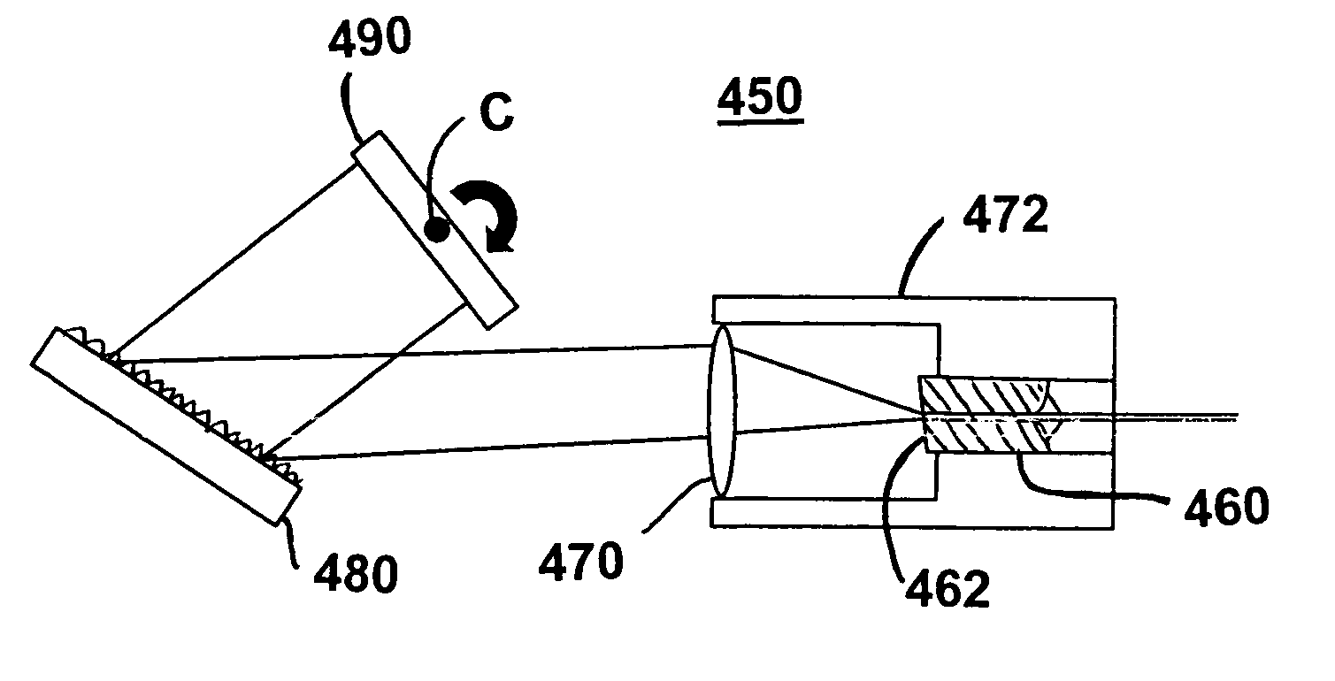
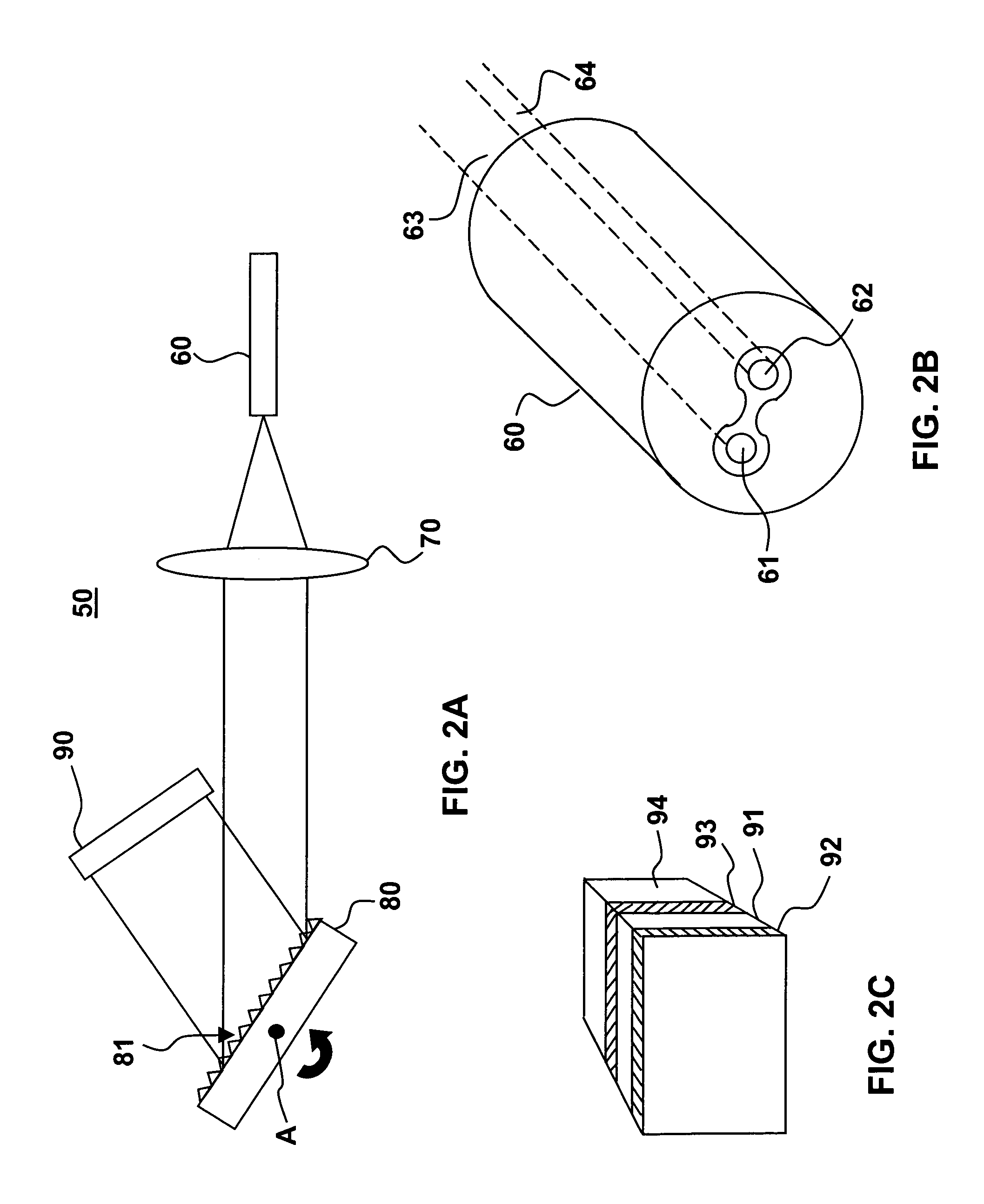
[0029]Referring to FIG. 2a there is shown a tunable optical filter having reduced PDL. The optical filter 50 includes an input / output fibre tube 60 that houses input and output optical fibres ends (61 and 62 in FIG. 2b), a collimating / focussing lens 70, a diffraction grating 80, and a reflective retarder 90. The diffraction grating 80 is rotatable about axis A, which is approximately parallel to the diffraction lines 81 of the grating and perpendicular to the plane of the figure.

[0030]In this embodiment, the diffraction grating 380 is a reflective grating. Alternatively, the diffraction grating 380 is replaced with a transmissive dispersive element. In this embodiment, the fibre tube 360 is a double bore tube as, for example, shown in FIG. 2b, wherein each bore holds one of the input and output optical fibre ends 61 and 62. Alternatively, the fibre tube has a different configuration that accommodates two fibre ends. Preferably, the ends 61, 62 of input and output optical fibres 63, ...


PUM


Abstract

A high-resolution tunable optical filter uses a dispersive element in a double pass configuration. The double pass configuration is provided by a reflective quarter-wave plate that conveniently reduces polarization dispersion loss (PDL) of the filter. The filter also includes a fibre tube for supporting an input optical fibre and an output optical fibre, and a lens having an optical axis, which is disposed such that a focal point thereof is substantially at one of the input and output optical fibres. To provide increase resolution the filter is tuned by rotating the reflective quarter-wave plate. To provide high power capabilities the fibre jackets of the input and output fibres are optionally stripped back. To provide a symmetrical spectral response the fibre tube is optionally mounted at an angle to the optical axis of the lens.

Description

CROSS-REFERENCE TO RELATED APPLICATIONS[0001]This application claims priority from U.S. Provisional Appl. No. 60 / 365,772 filed on Mar. 21, 2002.MICROFICHE APPENDIX[0002]Not ApplicableFIELD OF THE INVENTION[0003]The present invention relates generally to optical devices using a dispersive element in a double pass configuration and more particularly to a high resolution tunable optical filter.BACKGROUND OF THE INVENTION[0004]Optical filters have many applications in wavelength division multiplexing (WDM) systems, including but not limited to optical spectrum analysis, laser testing, wavelength demultiplexing, and amplified spontaneous emission filtering. Traditionally, optical filters have been based on fibre Bragg gratings (FBGs), thin film dielectric interference filters, Fabry-Perot filters, phased array waveguides, and diffraction gratings. The ideal optical filter is usually associated with flat channel passbands, low insertion loss, high isolation, low cost, high reliability and...

Claims


Application Information

Patent Timeline
Patent Type & Authority Patents(United States)
IPC IPC(8): G02B6/26G01J3/28G02B6/32G02B6/34G02B6/36G02B6/38
CPCG02B6/2931G02B6/29314G01J3/021G02B6/3833G02B6/327G02B6/3616
Inventor WEBER, JOHNZHU, XIANGWOODSIDE, SHANE H.
Owner LUMENTUM OPERATIONS LLC
Why Eureka
Try Eureka