Wavelength selective optical switch

a selective optical switch and wavelength technology, applied in the field of optical communication, can solve the problems of high installation cost of fiber optics, high cost of installing fiber optics, and high cost of aligning fibers for each wavelength, and achieve the effect of reducing pdl and reducing pdl

Inactive Publication Date: 2006-08-17
MCGUIRE JAMES P JR
View PDF42 Cites 7 Cited by
  • Summary
  • Abstract
  • Description
  • Claims
  • Application Information

AI Technical Summary

Benefits of technology

[0035] In accordance with several aspects of the invention one or more wave plates may be employed to reduce polarization dependent loss (PDL). The one or more wave plates rotates the polarization so that light that is s-polarized on a first pass is p-polarized on a second pass and there is no net polarization dependent loss (PDL) for light traveling through the device. Similarly, a polarization converter such as a rutile crystal may be used in combination with wave plates to reduce PDL.

Problems solved by technology

Despite the enormous information carrying capacity of fiber, as compared to conventional copper cable, the high cost of installing fiber optics presents a barrier to full implementation of fiber optics, particular as the “last mile”, from the central office to residences and businesses.
However, aligning the fibers for each wavelength is costly and errors in the alignment contribute significantly to the system losses.
As discussed above, aligning the collimators is expensive.
Polarization dependent loss (PDL) is also a problem in WDM system because the polarization of the light drifts as it propagates through the fiber and furthermore this drift changes over time.
Thus, if there is PDL in any component, the drifting polarization will change the signal level, which may degrade the system operation.
However, the multi channel OADM designs discussed above are not programmable by the end user.
This limitation mandates that the optical system's parameters be fixed before installation.
Changes are not possible without replacing the fixed optical multiplexers with different designed multiplexers.
A further limitation to Boisset et al. is that only a single channel may be added or dropped per device.
Designers may employ multiple devices, deployed in series, and programmed as necessary to add / drop the correct channel; however, this approach requires multiple devices and has multiple points of failure.
Furthermore, the size of such a device would be overly large and therefore not practical for many applications where space is limited.
The additional components require additional space, add attenuation, and add cost to the system.
Thus, the size and expense of the focusing lens required grows quickly when moving from a single to dual switching.
However, the size and expense of the lens required by the demultiplexer also grows linearly with port count.
Of course, a larger grating can be employed to increase the spectral resolving power, however, that requires a combination of more physical space and faster or longer focal length lenses that are more expensive.
Another approach has been to decrease the spacing of the grating grooves, d. However, the maximum theoretical efficiency of the grating decreases for small groove separations.
For even smaller grooves separations, it is not possible to get high efficiency in either polarization state.
Thus, there is a practical limit to increasing spectral resolving power through decreased grating groove separations.
The ability to switch to a number of optical ports in wavelength switches introduces another limiting design factor.
As the placement angle increases, the optical directing means generally becomes more expensive and the insertion loss increases.
An additional lens may be used to focus the beam—however, this adds component cost and size to the device.
The device disclosed by Marom cannot provide adequate spectral resolution for a large number of ports and a large number of wavelengths using small compact lenses that are easy to manufacture.
However, this design has a major drawback.
Thus, the device is unable to achieve adequate spectral resolution for a large number of ports and a large number of wavelengths with low losses.
However, because the cylindrical optics are used symmetrically to both collimate light for the grating and to focus the light on the switch array, the footprint of the optical beam at the switch is a very high aspect ratio ellipse.
Thus, very long thin, hard to fabricate switches are required.

Method used


Image

  • Wavelength selective optical switch
  • Wavelength selective optical switch
  • Wavelength selective optical switch

Examples


Embodiment Construction

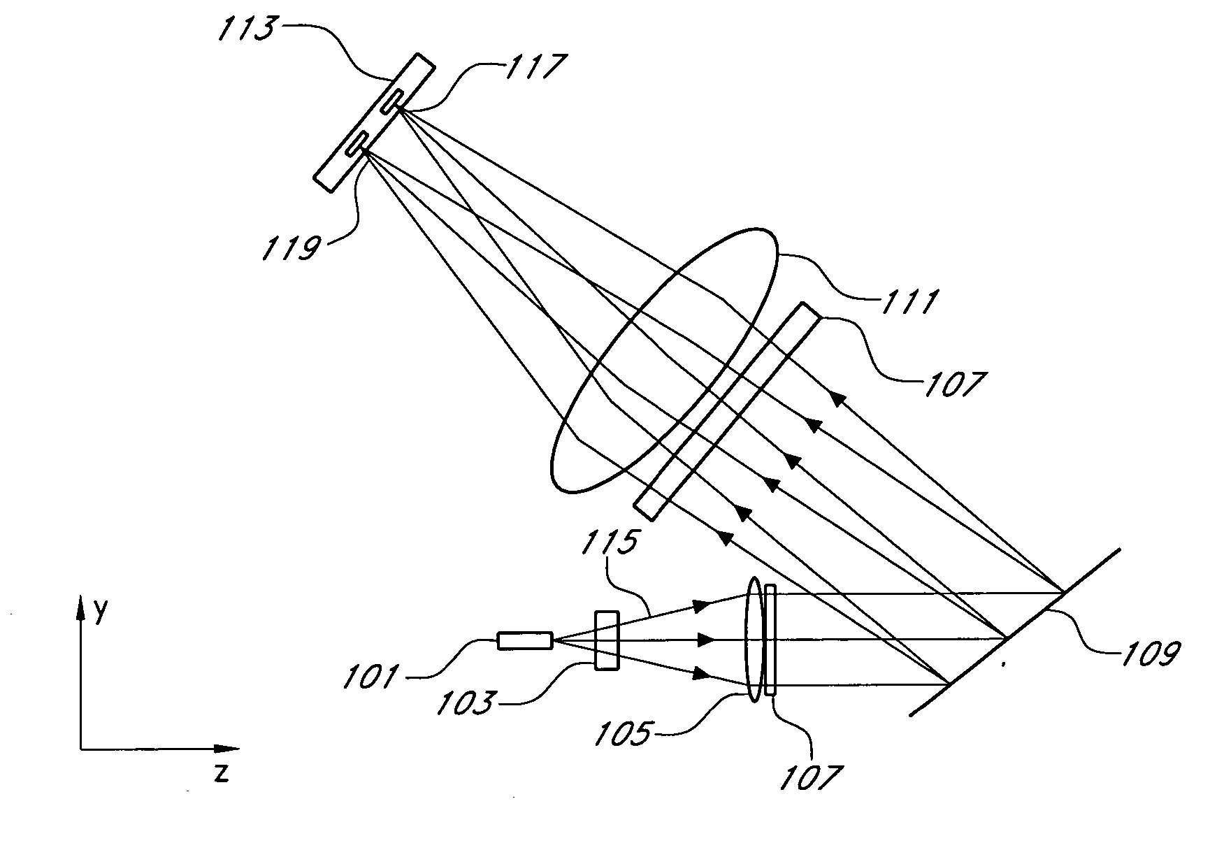
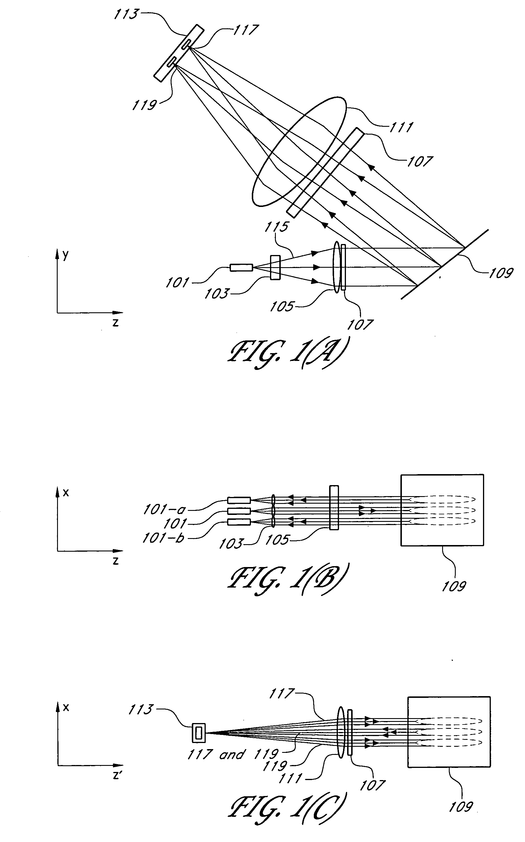
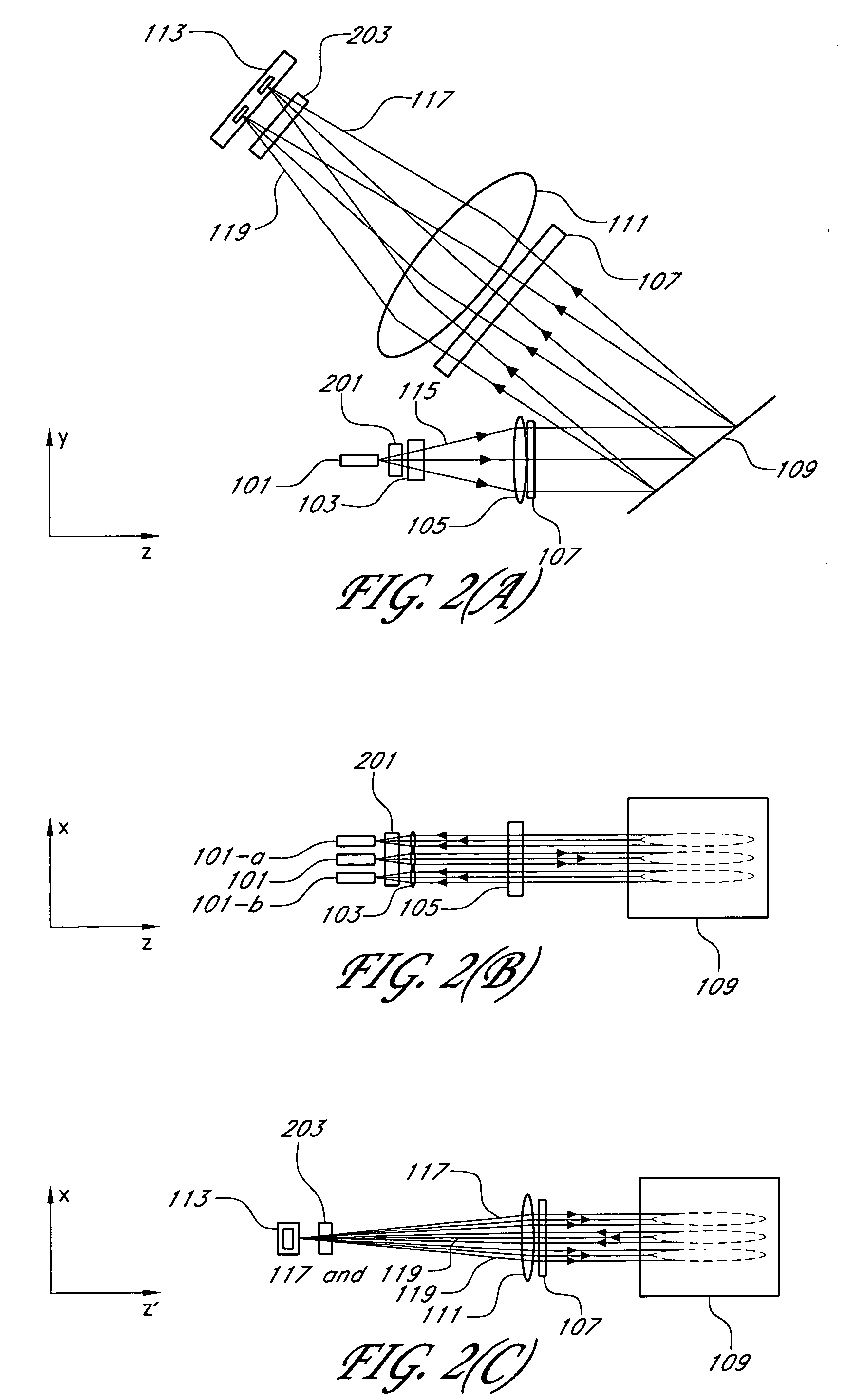
[0065] The wavelength selective optical switch of the invention has numerous applications, including use in fiber optic telecommunications systems. For purposes of illustration, the embodiments described below detail demultiplexing, switching, and multiplexing in a multi-channel fiber optic telecommunication systems. Exemplary references to an optical channel, or simply to a channel, should be understood to mean an optical signal with a centered wavelength and an upper and lower wavelength. Channel spacing is measured from the center of the first channel to the center of an adjacent channel.

[0066] A two channel grating-based optical switch, employing one embodiment of the invention, is detailed in FIG. 1(A), FIG. 1(B), and FIG. 1(C). FIG. 1(A), FIG. 1(B), and FIG. 1(C) detail different views of the same device. It is of note that while only two channels are used in this example, a substantially larger number of channels and optical ports may be employed. The wavelength selective op...


PUM


Abstract

A wavelength selective optical switch particularly usable as a programmable N×M optical switch in a multi-wavelength communication system. The switch uses a grating that separates multi-channel optical signals into a plurality of optical channels, and combines a plurality of optical channels into multi-channel optical signals. Programmable mirrors switch each optical channel to any of a plurality of fibers coupled to the switch.

Description

RELATED APPLICATION [0001] This application claims priority of U.S. Provisional Application Nos. 60 / 388,358 filed Jun. 12, 2002, and 60 / 397,944 filed Jul. 23, 2002, the disclosures of which are incorporated fully herein by reference.FIELD OF THE INVENTION [0002] This invention relates to the field of optical communications, and more particularly, to a wavelength selective optical switch for use in optical multiplexing. BACKGROUND OF THE INVENTION [0003] For several decades, fiber optics have been used for communication. Specifically, fiber optics are used for data transmission and other telecommunication applications. Despite the enormous information carrying capacity of fiber, as compared to conventional copper cable, the high cost of installing fiber optics presents a barrier to full implementation of fiber optics, particular as the “last mile”, from the central office to residences and businesses. [0004] One method of increasing carrying capacity without incurring additional inst...

Claims


Application Information

Patent Timeline
Patent Type & Authority Applications(United States)
IPC IPC(8): G02B6/26G02B6/42G02B6/34G02B6/35
CPCG02B6/2706G02B6/272G02B6/2793G02B6/29307G02B6/2931G02B6/29311G02B6/29313G02B6/29373G02B6/2938G02B6/29395G02B6/29398G02B6/35G02B6/3512G02B6/356G02B6/3592
Inventor MCGUIRE, JAMES P. JR.
Owner MCGUIRE JAMES P JR
Why Eureka
Try Eureka