Microstrip reflectarray antenna

a microstrip reflector and antenna technology, applied in the direction of antennas, antenna details, basic electric elements, etc., can solve the problems of insufficient operation of conventional satellite communication systems, high operating frequency range of channel signal transmission, and high operating frequency range of available operation frequency range of channel signal transmission systems, etc., to achieve the effect of reducing the cross polarization level of microstrip reflector antennas, facilitating the expansion of satellite communication systems, and improving reception quality

Inactive Publication Date: 2008-01-31
TATUNG UNIVERSITY +1
View PDF6 Cites 33 Cited by
  • Summary
  • Abstract
  • Description
  • Claims
  • Application Information

AI Technical Summary

Benefits of technology

[0011]Therefore, as each microstrip antenna unit of the microstrip reflectarray antenna of the present invention consists of an outer ring having two first slots, and an inner ring having two second slots, wherein the connecting line connecting the two first slots (not shown in the figure) is parallel to the other connecting line connecting the two second slots (not shown in the figure), the microstrip antenna units of the microstrip reflectarray antenna of the present invention can prevent the current induced by a high frequency signal having a polarization direction perpendicular to the connecting line of the two first slots from flowing on the microstrip antenna units when the microstrip reflectarray antenna of the present invention is in its “receiving state”. As a result, the microstrip reflectarray antenna of the present invention can only receive the high frequency signals having the polarization direction parallel to the connecting line of the two first slots of the microstrip antenna units, and the cross polarization level of the microstrip reflectarray antenna is further reduced. Hence, by using the microstrip reflectarray antenna of the present invention, a satellite communication system can use one frequency channel to transmit two or more signals with different polarization directions at the same time. Thus, the capacity of the satellite communication system is enlarged, and the reception quality thereof is also improved.

Problems solved by technology

In a conventional satellite communication system such as satellite TV, the available operation frequency range of the channel signal transmission is highly restricted by the absorption of the atmosphere or other related factors.
Currently, as the number of the channels to transmit channel signals increases significantly, i.e. hundreds of cable TV channels, the conventional satellite communication system, which uses different frequencies to transmit different channel signals (i.e. frequency multiplexing method), is no longer sufficient for operation.
As a result, there is not immediate need to launch new satellites, which results in saving a huge amount of money.

Method used


Image

  • Microstrip reflectarray antenna
  • Microstrip reflectarray antenna
  • Microstrip reflectarray antenna

Examples


Embodiment Construction

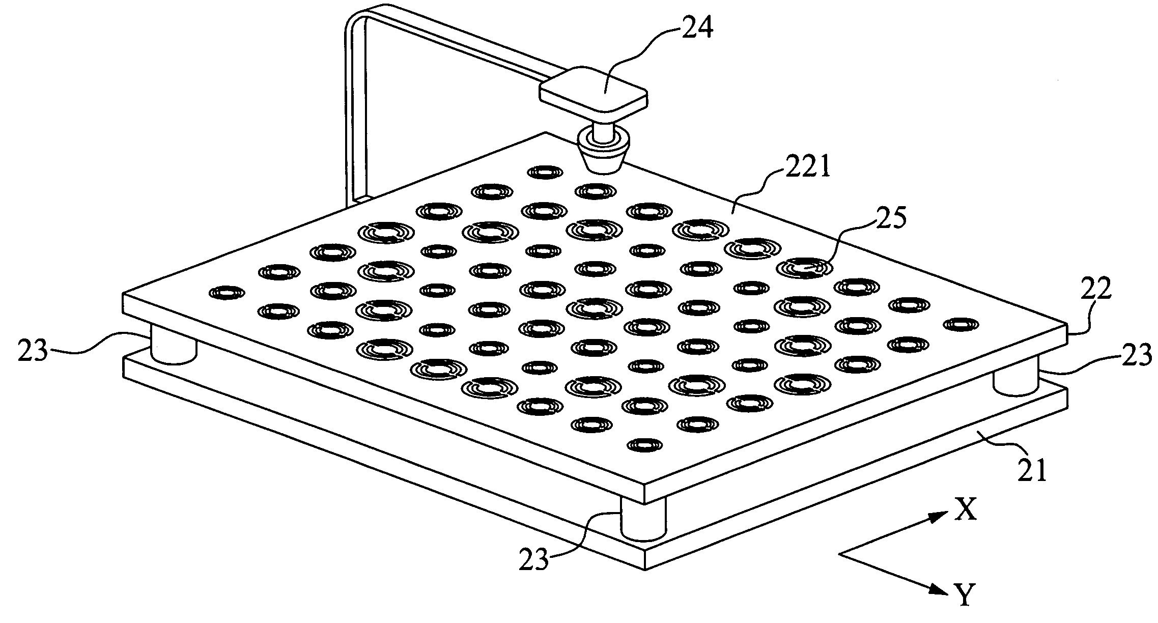
[0024]FIG. 2A shows a schematic diagram of the microstrip reflectarray antenna according to the first preferred embodiment of the present invention. In the present preferred embodiment, the microstrip reflectarray antenna comprises a ground plate 21, a reflecting plate 22, four supporting units 23, and a horn antenna 24. The reflecting plate 22 is supported by the four supporting units 23 being composed of at least one insulating material, and thus a predetermined distance between the reflecting plate 22 and the ground plate 21 being composed of copper is maintained. In the present preferred embodiment, the distance between the reflecting plate 22 and the ground plate 21 is about 6 mm. But, as in different operation environments, the distance between the reflecting plate 22 and the ground plate 21 can be varied by adjusting the length of the four supporting units 23. With reference to FIG. 2B, the microstrip reflectarray antenna according to the first preferred embodiment of the pre...


PUM


Abstract

A microstrip reflectarray antenna with a low cross polarization level is disclosed. The microstrip reflectarray antenna of the present invention comprises: a ground plate; a reflecting plate with an upper surface, and a plurality of microstrip antenna units locating on the upper surface; each of the microstrip antenna units consisting of an inner ring and an outer ring; a plurality of supporting units for supporting the reflecting plate above the ground plate; and a signal transmitting unit locating above the reflecting plate for transmitting and receiving the high frequency signal. Besides, the size of the outer ring corresponds to its location on the upper surface of the reflecting plate, and there is a predetermined ratio between the diameter of the outer ring and the diameter of the inner ring, and both of the outer ring and the inner ring respectively have at least one slot.

Description

BACKGROUND OF THE INVENTION[0001]1. Field of the Invention[0002]The present invention relates to a microstrip reflectarray antenna and, more particularly, to a microstrip reflectarray antenna with lower cross polarization level for operation in a satellite communication system.[0003]2. Description of Related Art[0004]In a conventional satellite communication system such as satellite TV, the available operation frequency range of the channel signal transmission is highly restricted by the absorption of the atmosphere or other related factors. Currently, as the number of the channels to transmit channel signals increases significantly, i.e. hundreds of cable TV channels, the conventional satellite communication system, which uses different frequencies to transmit different channel signals (i.e. frequency multiplexing method), is no longer sufficient for operation. As a result, another conventional satellite communication system, which uses a plurality of same frequency signals having ...

Claims


Application Information

Patent Timeline
Patent Type & Authority Applications(United States)
IPC IPC(8): H01Q1/38
CPCH01Q1/38H01Q15/14H01Q3/46
Inventor CHANG, THE-NANCHU, CHUNG-SUNG
Owner TATUNG UNIVERSITY
Why Eureka
Try Eureka