Liquid crystal display apparatus

a technology of liquid crystal display and display device, which is applied in non-linear optics, instruments, optics, etc., can solve the problems of polarization degree collapse and other problems, and achieve the effects of reducing the luminance of the black representation thereof, reducing the blue changing phenomenon of the black representation, and high contrast ratio

Inactive Publication Date: 2006-03-30
PANASONIC LIQUID CRYSTAL DISPLAY CO LTD +1
View PDF8 Cites 33 Cited by
  • Summary
  • Abstract
  • Description
  • Claims
  • Application Information

AI Technical Summary

Benefits of technology

[0042] As previously described in detail, in accordance with the liquid crystal display apparatus of the present invention, the luminance of the black representation thereof is lowered, and the high contrast ratio is ach

Problems solved by technology

Also, as represented in the characteristics indicated by the solid line and the br

Method used


Image

  • Liquid crystal display apparatus
  • Liquid crystal display apparatus
  • Liquid crystal display apparatus

Examples


embodiment 1

[0057] An embodiment 1 according to the present invention will now be explained with reference to drawings.

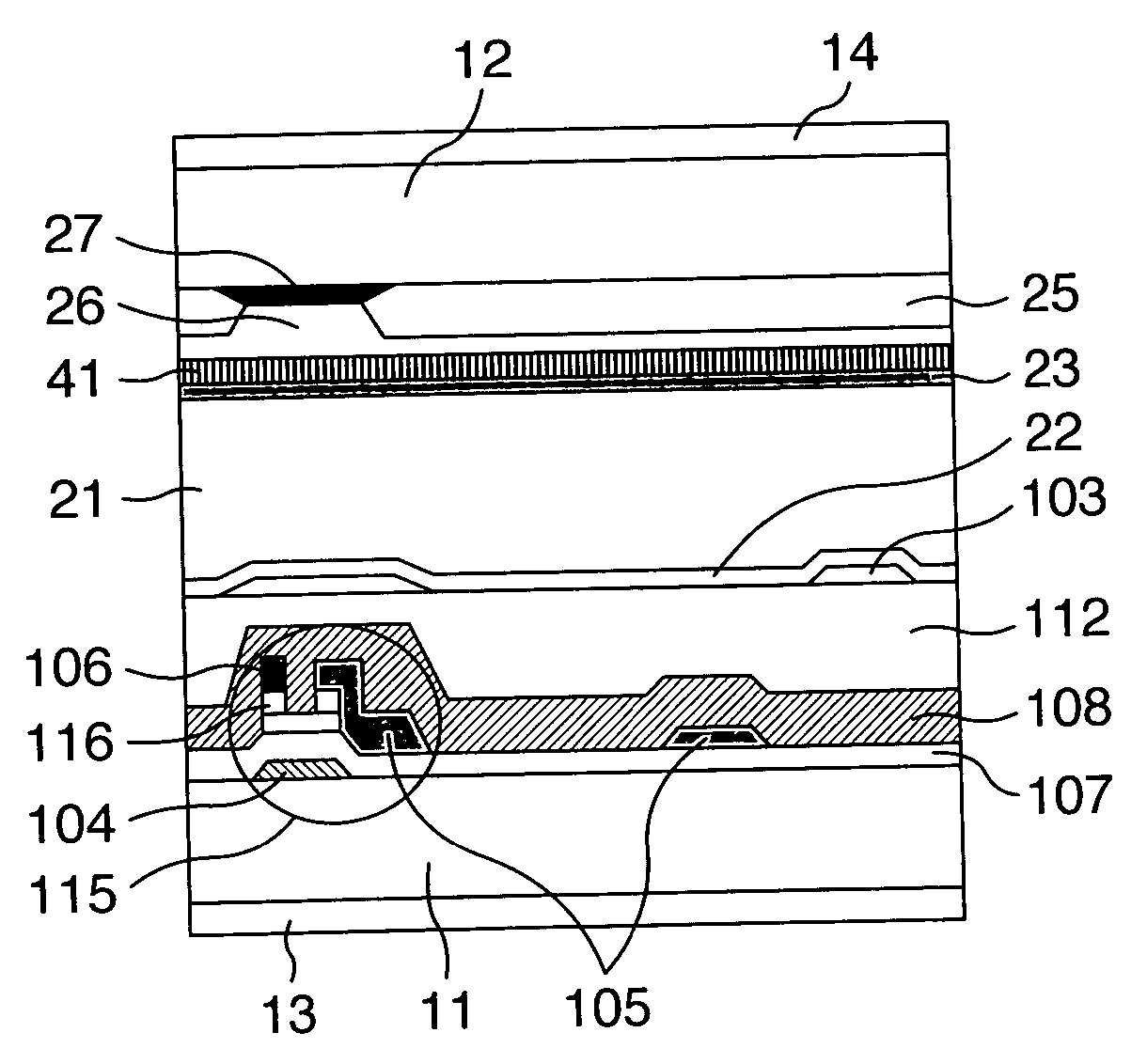
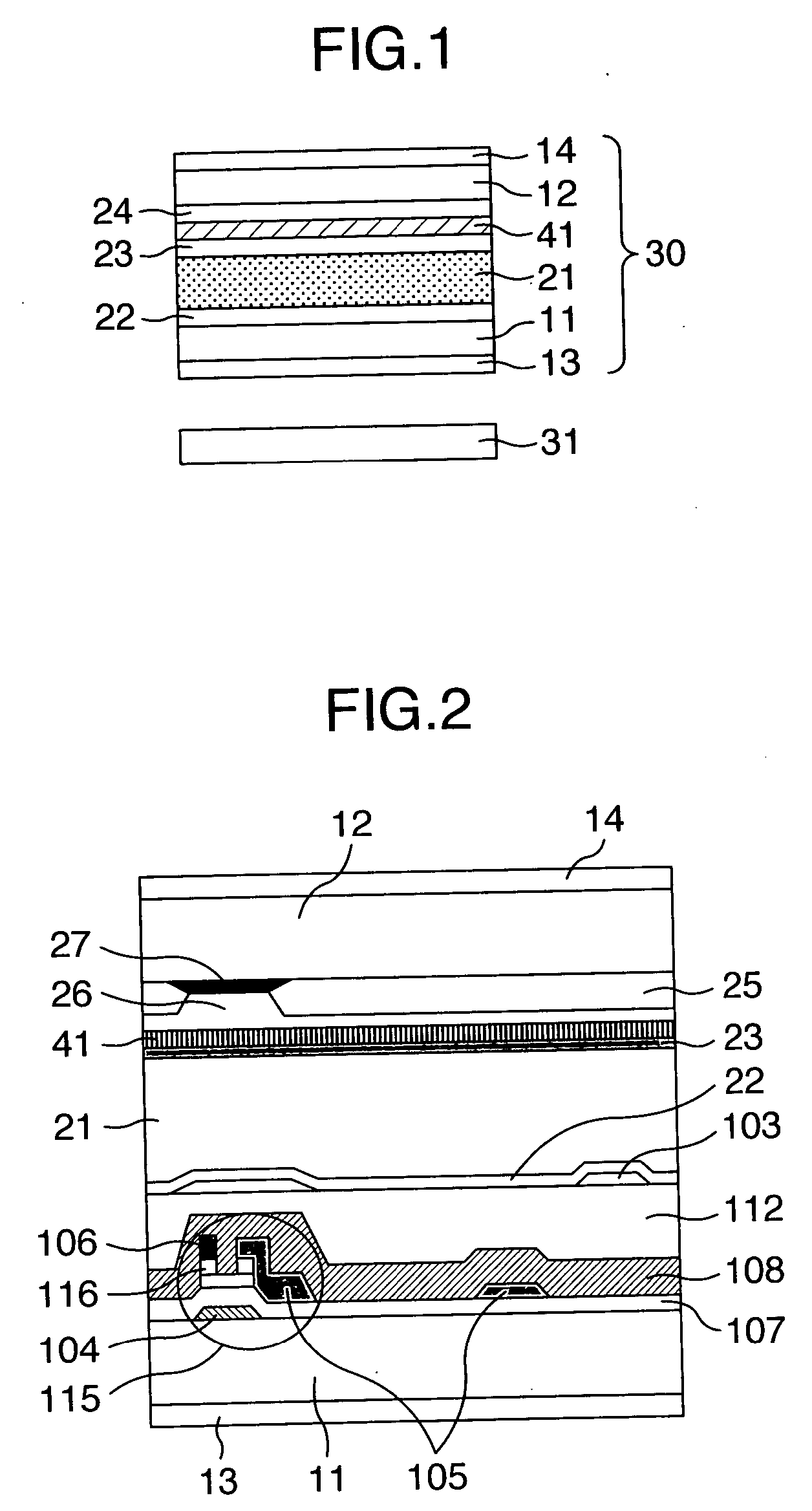
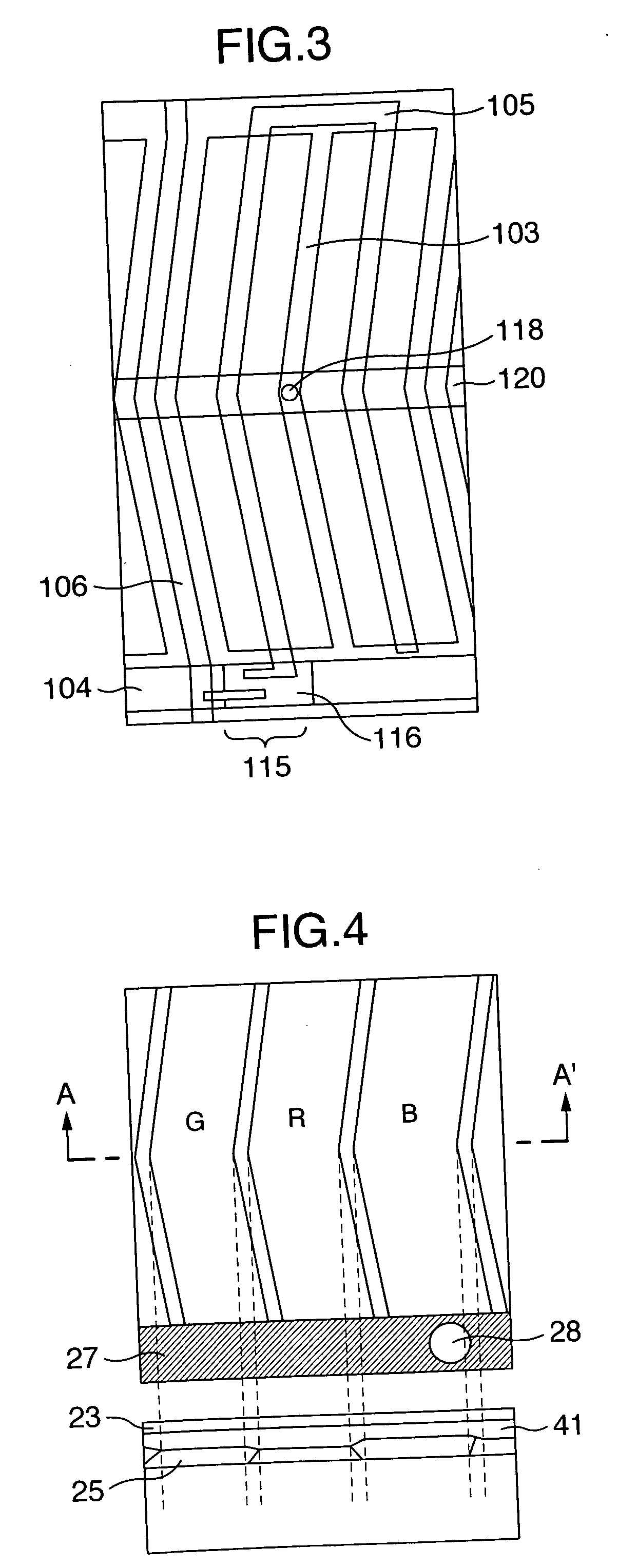
[0058]FIG. 2 is a sectional view for schematically representing an area in the vicinity of one pixel, which explains an embodiment mode 1 of a liquid crystal display apparatus according to the present invention.FIG. 3 is a schematic diagram for showing an area in the vicinity of one pixel of an active matrix substrate, which explains the embodiment mode 1 of the liquid crystal display apparatus according to the present invention. FIG. 4 is a schematic diagram for indicating an area in the vicinity of one picture element (R, G, B pixels) of a color filter substrate.

[0059] While a liquid crystal display apparatus corresponding to a first embodiment of the present invention is manufactured, a non-alkali glass substrate having a thickness of 0.7 mm was employed as both a substrate 11 which constitutes an active matrix substrate, and another substrate 12 which constitutes a color ...

embodiment 2

[0068]FIG. 5 and FIG. 6 are sectional views for schematically representing an area in the vicinity of one pixel, which explains an embodiment mode 2 of a liquid crystal display according to the present invention. Also, FIG. 7 is a schematic diagram for showing an active matrix substrate for explaining a structure of an area in the vicinity of one pixel used to explain the liquid crystal display according to the resent invention. FIG. 8 is a schematic diagram for describing a structure of an area in the vicinity of one picture element (R, G, B pixels) of a color filter substrate.

[0069] S In this second embodiment, a common electrode 103 made of ITO (indium-tin-oxide) has been arranged on a substrate 11 provided as an active matrix substrate; both a scanning electrode (gate electrode) 104 and a common electrode wiring line (common wiring line) 120, which are made of Mo / Al (molybdenum / aluminium), have been formed in such a manner that these scanning electrode 104 and common electrode ...

embodiment 3

[0082] In this third embodiment, a monoaxial absorption anisotropic layer 41 has been formed on a color filter substrate of a vertical alignment mode (PVA) type liquid crystal display device indicated in FIG. 9.

[0083] As to the color filter substrate, chromium having a thickness of 160 nm and a chromium oxide film having a thickness of 40 nm were formed by way of a continuous sputtering method on a non-alkali glass substrate 12 having a thickness of 0.7 mm, and then, a positive type resist was processed through various steps, namely, a coating step, a pre-baking step, an exposing step, a developing step, an etching step, a stripping step, and a cleaning step. Next, while the respective color resists made by Fuji Film Arch Company were employed, a color filter was formed by performing a photolithography method (namely, standard processing method) through various steps, namely, a coating step, a pre-baking step, an exposing step, a developing step, a rinsing step, and a post-baking s...


PUM


Abstract

A liquid crystal display apparatus including one pair of substrates, at least one of said substrates being transparent, one pair of polarizing plates arranged on the paired substrates respectively, a liquid crystal layer sandwiched by the paired substrates, a liquid crystal display panel in which an electrode group is formed on at least one of the paired substrates and is to apply an electric field to the liquid crystal layer, and a light source unit arranged on a rear surface of the liquid crystal display panel, a monoaxial absorption anisotropic layer provided between the paired polarizing plates. In such apparatus, a high contrast ratio can be achieved due to suppression of black luminance. Also, better display qualities can be achieved by reducing a blue changing phenomenon of black representation.

Description

BACKGROUND OF THE INVENTION [0001] 1. Field of the Invention [0002] The present invention is related to a liquid crystal display panel substrate containing a member representative of monoaxial absorption anisotropy, and related to a liquid crystal display panel, and also to a liquid crystal display apparatus, which use this liquid crystal display panel substrate. [0003] 2. Description of the Related Art [0004] Usage of liquid crystal displays has been expanded because of the following merits, namely liquid crystal displays can be made slim and in light weight, and further, viewing angle enlarging techniques and moving picture techniques have been developed / progressed, as compared with CRTs (cathode-ray tubes; generally speaking, will be referred as “Braun tubes”) which may constitute a major component of conventional display apparatus. [0005] Very recently, the usage of such liquid crystal displays has been expanded as monitors used in desk-top type personal computers, monitors used...

Claims


Application Information

Patent Timeline
IPC IPC(8): G02F1/1335
CPCG02F1/133509G02F2201/08G02F2001/133565G02F1/133528G02F1/133565G02F1/1335G02F1/1337
Inventor UTSUMI, YUKATOMIOKA, YASUSHIMATSUMORI, MASAKIMATSUYAMA, SHIGERUKUNIMATSU, NOBORUYAMAMOTO, TSUNENORI
Owner PANASONIC LIQUID CRYSTAL DISPLAY CO LTD
Why Eureka
Try Eureka