
Sealing member for spark plug

a sealing member and spark plug technology, applied in spark plugs, machines/engines, mechanical equipment, etc., can solve the problems of relatively low durability, increased vibration of engines, and increased temperature in combustion chambers, so as to improve the workability of sealing members, the degree of deformation of sealing members can be adjusted, and the rigidity high

Active Publication Date: 2011-11-29
NGK SPARK PLUG CO LTD
View PDF6 Cites 2 Cited by
  • Summary
  • Abstract
  • Description
  • Claims
  • Application Information

AI Technical Summary

Benefits of technology

The present invention relates to a sealing member for a spark plug that can provide a sufficient axial force with a low tightening torque. The sealing member is made of annular sheet material made of stainless steel and is folded back in a radial direction to form a region where at least two layers of the sheet material are overlaid in an axial direction. The sealing member is compressed in the axial direction between an annular-shaped projecting portion of the metal shell of the cylindrical spark plug and an opening circumference edge portion of a mounting hole to provide a seal. The sealing member satisfies the following relations: 0.20.5 0.5≤n≤5 1.1 L≤x≤1.4 L 0.2≤n The sealing member is designed to have high rigidity and durability over a creep deformation caused by heating and cooling cycle during an engine drive and stop. The sealing member can be easily mounted on the spark plug and provides a secure seal during operation.

Problems solved by technology

As internal combustion engines have been miniaturized and advanced in recent years, engine vibration tends to increase, and a temperature in the combustion chamber tends to rise.
Because a gasket made of the conventional Fe has relatively low durability over a creep deformation, which is caused by heating and cooling cycles during an engine drive and stop, the spark plug mounted on an engine tends to come loose, resulting in deterioration in the axial force.
However, along with the miniaturization of internal combustion engines, spark plugs have also been miniaturized.
Since a gasket made of stainless steel with a high rigidity is unlikely to plastically deform, sufficient axial force after tightening the spark plug cannot be obtained when the tightening torque is low.
As a result, the air tightness in the combustion chamber becomes insufficient.
On the other hand, when the tightening torque is raised in order for a gasket to sufficiently deform plastically, stress exerted to a thread neck of a metal shell, which has a low durability due to its miniaturization, increases, resulting in a possible fracture or the like of the spark plug.

Method used


Image

  • Sealing member for spark plug
  • Sealing member for spark plug
  • Sealing member for spark plug

Examples


first embodiment

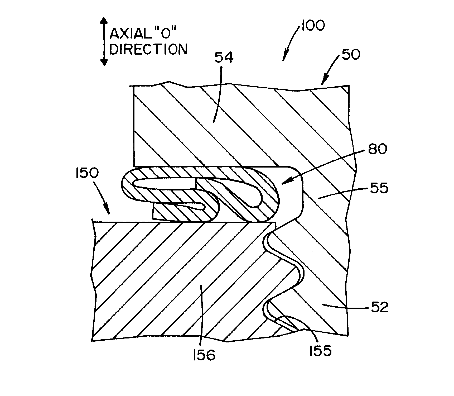
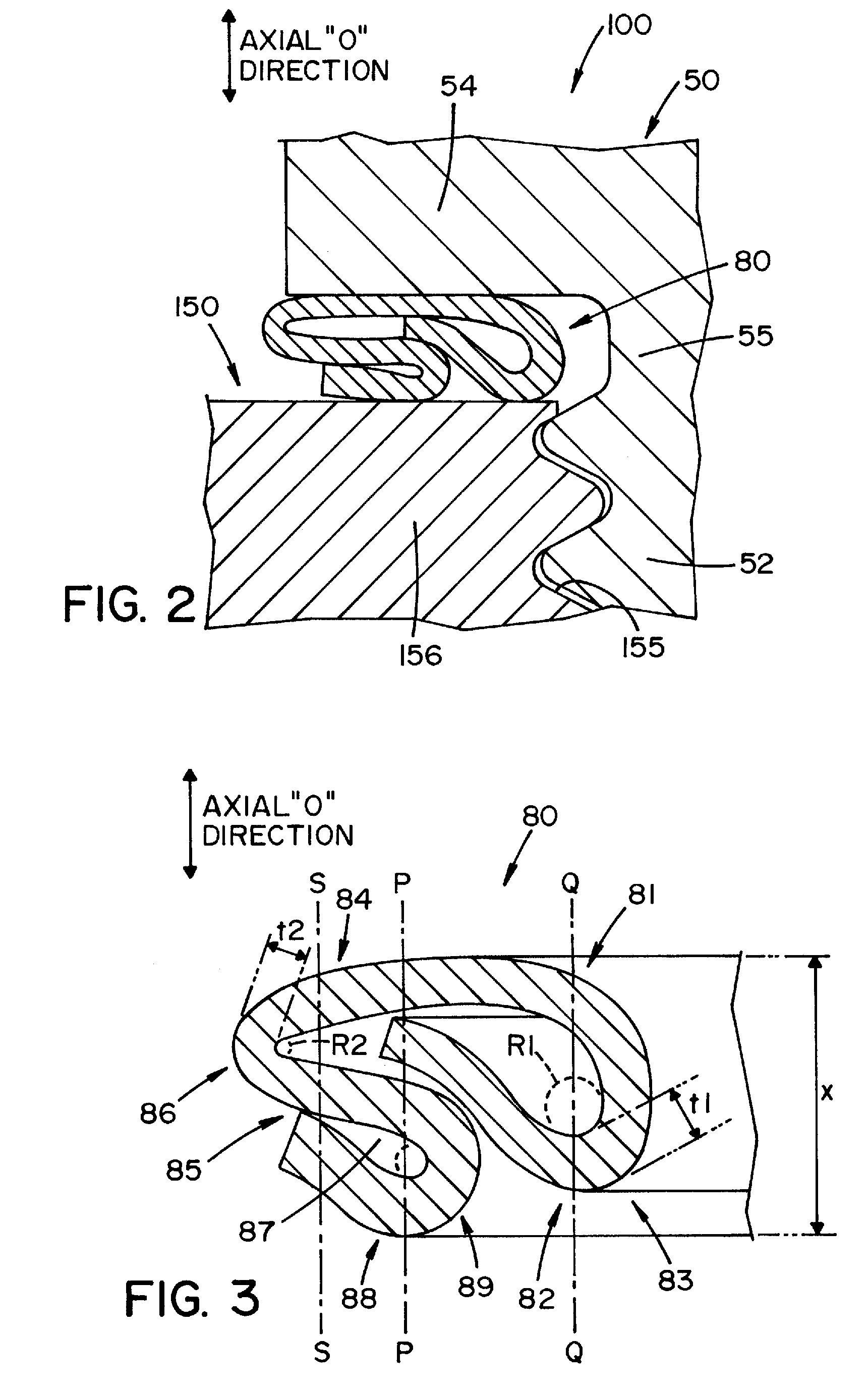
[0072]First, an evaluation test for determining a lower limit of the entire thickness “x” of the gasket was conducted. In this test, a sheet of stainless steel was formed into an annular shape with the average thickness “|” of 0.3 mm, and a plurality of thus-formed sheet materials was prepared. As shown in FIG. 3, each sheet material was subjected to a bending process using a mold so that the number of layers “n” of the sheet material was 4 in a region having the greatest number of overlapping layers in the axial “O” direction. At this time, the mold was adjusted so that each entire thickness “x” of the gasket after the bending process was made to fall within the range from 1.0 L to 1.65 L. Fifty samples of each thickness “x” for M12 were produced.

[0073]The thus-formed samples were provided on spark plugs for the test. In order to prevent the gasket from falling off, an inwardly projecting region was formed where a part of the gasket on the inner hole side was slightly deformed. The...

second embodiment

[0075]Next, the evaluation test for confirming an upper limit of the entire thickness “x” of the gasket was conducted. Similar to the first embodiment, in this embodiment, a plurality of sheet materials constituting the gasket and made of stainless steel (SUS) with the average thickness “|” of 0.3 mm was prepared. Then, the sheet materials were subjected to bending process so that the number of layers “n” of the sheet material was “4” in the region having the greatest number of overlapping layers in the axial “O” direction. The entire thickness “x” of the gasket after the bending process was made to fall within the range from 1.0 L to 1.85 L. A plurality of gasket samples for M12 was prepared. Further, for comparison, gasket samples having the same shape as that of the above samples and an entire thickness of 1.8 L (2.16 mm) were produced using a sheet material made of Fe with the average thickness of 0.3 mm.

[0076]Thus-produced samples were provided on spark plugs for the test, resp...

third embodiment

[0078]Next, similar to the second embodiment, an evaluation test was conducted on a gasket for a spark plug that has a nominal diameter of M12. Similar to the above, in this evaluation test, a plurality of gasket samples made of stainless steel and satisfying the following conditions was prepared for an M12 spark plug. The average thickness “|” of the sheet material constituting the gasket was 0.4 mm, and the number of layers “n” of the sheet material was 3 in the region having the greatest number of overlapping layers in the axial “O” direction. The entire thickness “x” of the gasket after the bending process was made to fall within the range from 1.0 L to 1.85 L. Further, for comparison, gasket samples having the same shape as that of the above samples and an entire thickness of 1.85 L (2.16 mm) were produced using a sheet material made of Fe with the average thickness of 0.4 mm. When the evaluation test was conducted by the same method as the second embodiment, as shown in FIG. 7...


PUM


Abstract

A sealing member for a cylindrical spark plug having a metal shell with threaded ridges thereon to be screwed into a mounting hole of a combustion engine, the sealing member comprised of a piece of annular sheet material made of austenitic stainless steel or ferritic stainless steel that is folded back in a radial direction so as to form a region where at least two or more layers of the sheet material are overlapped in an axial direction.

Description

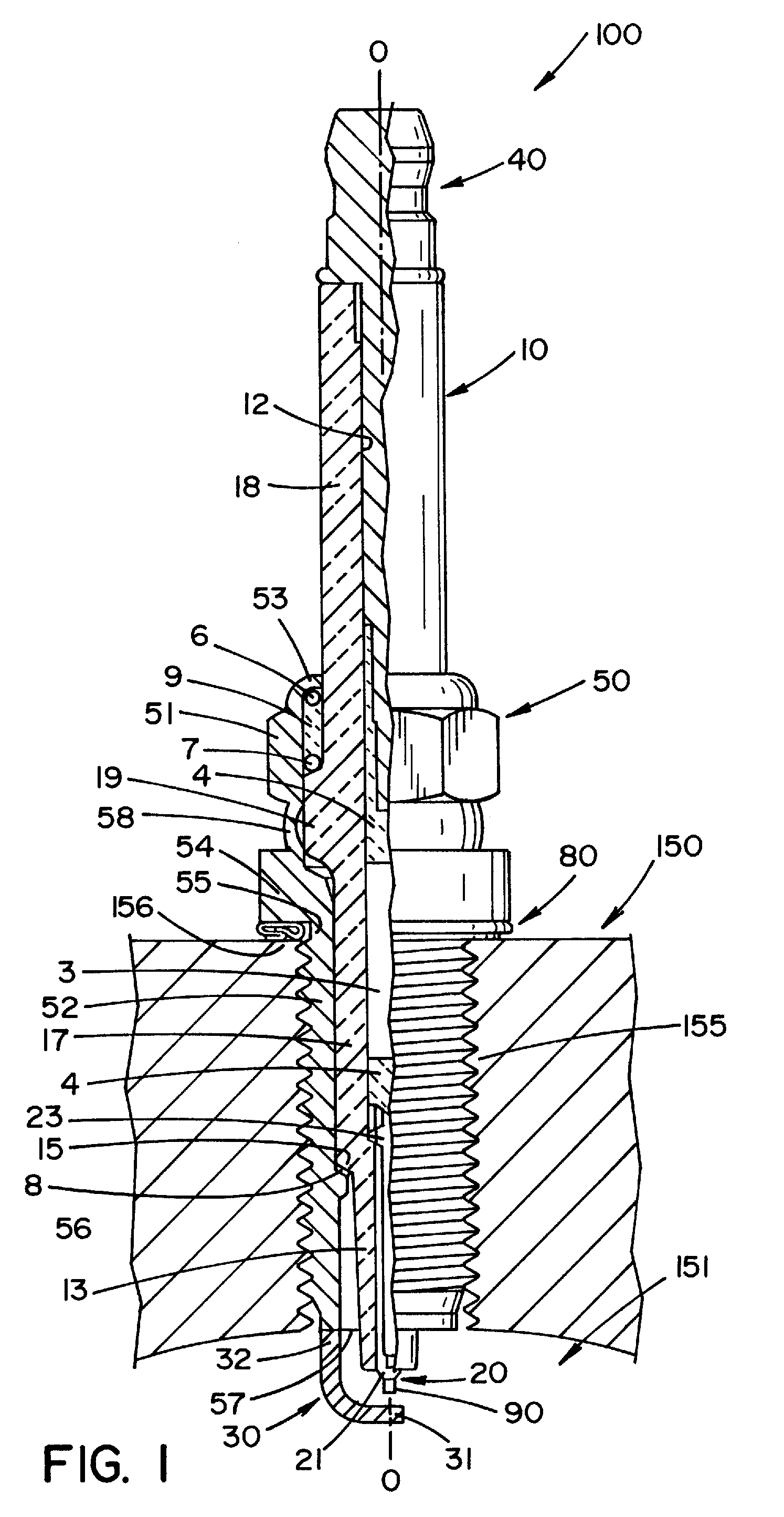
FIELD OF THE INVENTION[0001]The present invention relates to a spark plug and more particularly to a sealing member that is provided around a metal shell of a spark plug that is to be mounted on a mounting hole of an internal combustion engine to thereby seal air leakage through the mounting hole.BACKGROUND OF THE INVENTION[0002]A conventional spark plug is mounted on an internal combustion engine by screwing a thread ridge formed on an outer circumference of a metal shell into a female screw formed on a mounting hole of an engine head of the internal combustion engine. Such a spark plug includes an annular sealing member (a gasket) provided on the outer circumference of the metal shell in order to prevent an air leakage from a combustion chamber through the mounting hole. A conventional gasket is formed from an annular shaped cold-rolling strip (hereafter referred to as “Fe”). The annular strip is folded back in the radial direction so as to assume, for example, an “S” shape in the...

Claims


Application Information

Patent Timeline
Patent Type & Authority Patents(United States)
IPC IPC(8): H01T13/04H01T13/20
CPCH01T13/08F02P13/00
Inventor FUKUZAWA, REIMONKATO, TOMOAKI
Owner NGK SPARK PLUG CO LTD
Learn More