Eccentric cam brake booster

a technology of brake booster and eccentric cam, which is applied in the direction of braking system, rotary clutch, fluid coupling, etc., can solve the problem of deploying a rather complex mechanical coupling between the motor and the master cylinder piston rod, and achieves low noise, good response time, and high gain capability

Active Publication Date: 2011-12-06
ROBERT BOSCH CORP +1
View PDF7 Cites 51 Cited by
  • Summary
  • Abstract
  • Description
  • Claims
  • Application Information

AI Technical Summary

Benefits of technology

[0015]An advantage of the present invention is that the cam profile is adjustable for different applications.
[0016]Another advantage is a v

Problems solved by technology

Each employs a rather complex mechanical coupling

Method used


Image

  • Eccentric cam brake booster
  • Eccentric cam brake booster
  • Eccentric cam brake booster

Examples


Embodiment Construction

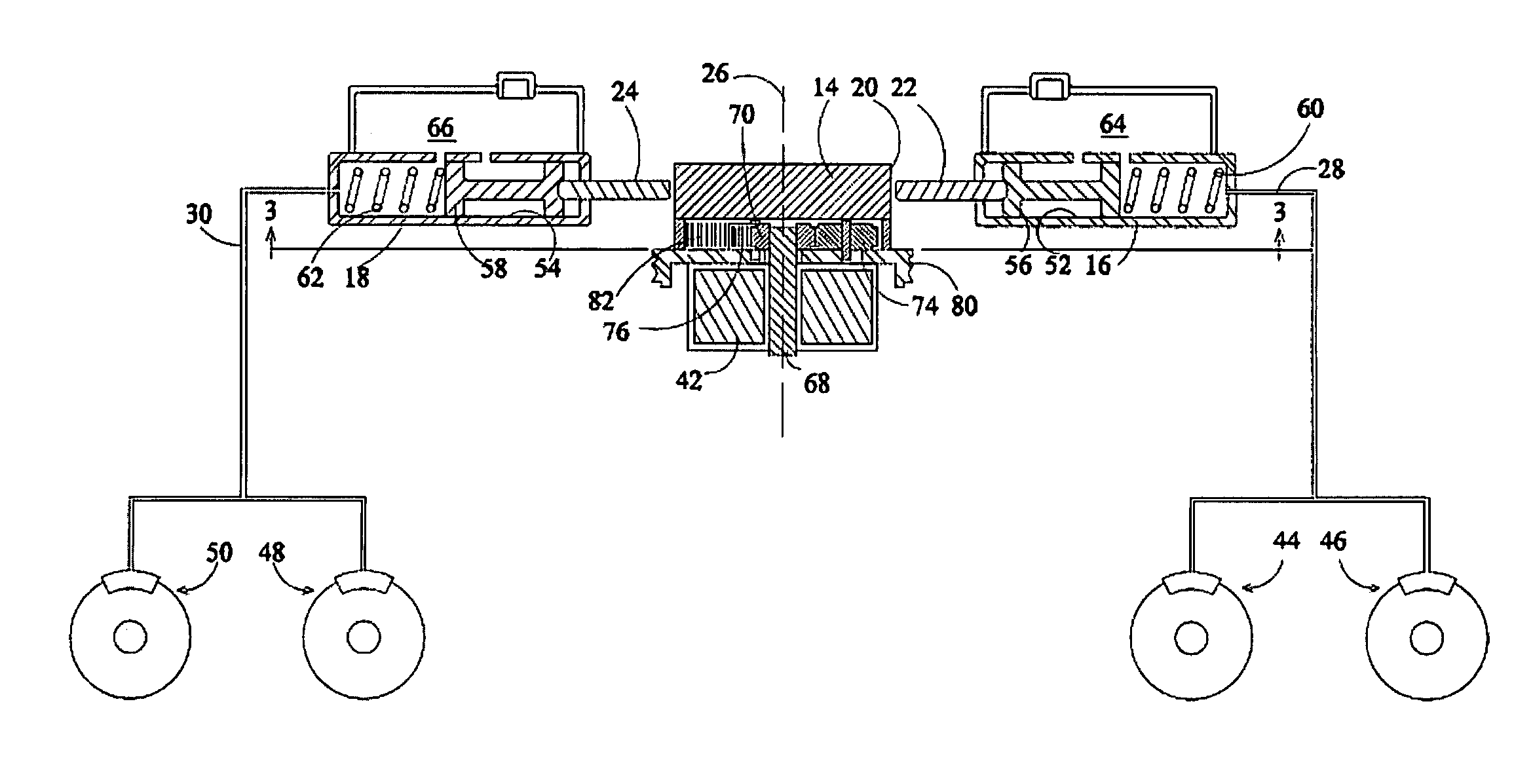
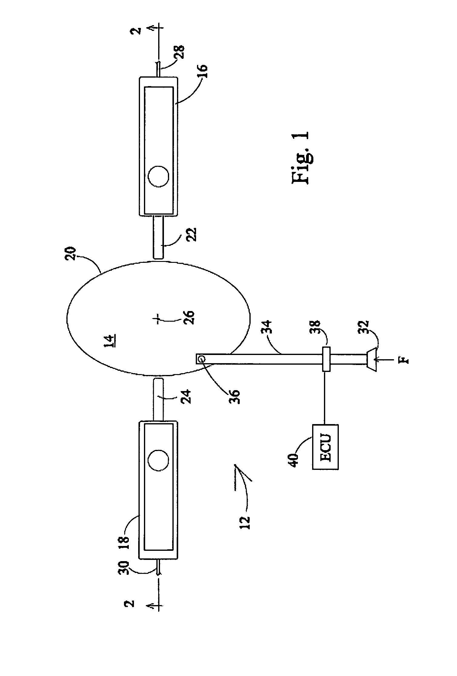
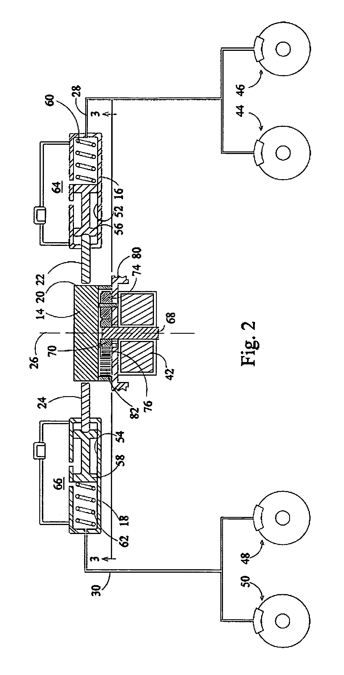
[0024]Referring now to the drawings and particularly to FIG. 1, there is shown an electric booster 12 with cam 14 for actuating opposing master cylinders 16 and 18. The cam has a variable radius surface 20 which engages respective piston actuating rods 22 and 24. The portion of cam surface 20 between 0 and 90 degrees and that between 270 and 360 degrees as viewed in FIG. 1 are opposed symmetric surfaces and the only portions of surface 20 utilized in actuating the piston rods. Cam axis 26 is a two-fold axis of symmetry, that is, rotation of the cam about the axis by 180 degrees results in a cam surface 20 configuration which is indistinguishable from the original. The cam is illustrated a being generally elliptical, but numerous other cam surface configurations are easily envisioned. As the cam 14 rotates about axis 26, the effective cam radius (distance from the center to the end of a piston actuating rod) continuously increases depressing the actuating rod and pressurizing respect...


PUM


Abstract

An electric power booster (12) where driver command is monitored by a transducer (38) on an input rod (34). This signal is converted to the appropriate voltage/current and operates an electric motor (42). The motor output shaft (68) is connected to a planetary gear reducer (72) appropriately sized to provide no more than +/−1/4 turn of an eccentric cam (14). Two master cylinders (16, 18) power piston rods (22, 24) ride diametrically opposed on the cam surface (20). As the cam rotates the piston rods are forced out pressurizing the respective hydraulic circuits and thereby providing fluid to each brake circuit (28, 30). In the event of power failure as well as to augment the output of the motor, the input rod is mechanically linked directly to the cam offset from the center allowing the driver to manually rotate the cam thereby pressurizing the brake circuits.

Description

BACKGROUND OF THE INVENTION[0001]1. Field of the Invention[0002]The present invention relates to vehicle brake systems and more particularly to an improved electric power booster.[0003]2. Description of the Related Art[0004]Many of today's vehicles are equipped with power-braking systems to reduce a driver's brake pedal effort. Most use a vacuum to increase braking power. An engine's pistons create a vacuum as they draw air into the engine. The engine intake manifold vacuum is connected by a tube to both sides of a special spring-loaded diaphragm located in a housing intermediate an operator brake actuating pedal mechanism and a master cylinder. When the operator actuates the brake pedal, atmospheric pressure is admitted to one side of the diaphragm supplying additional force to the master cylinder piston and enhanced brake line pressure to the individual wheel cylinders. Vehicle braking is still possible in the event of vacuum source failure since brake pedal pressure may still be ...

Claims


Application Information

Patent Timeline
IPC IPC(8): F15B7/08B60T7/04
CPCB60T7/107B60T13/745
Inventor ALBERT, TIMOTHY J.
Owner ROBERT BOSCH CORP
Why Eureka
Try Eureka