Gate valve for vacuum and seal member used therefor

a technology of vacuum and seal member, applied in the direction of valve housing, valve arrangement, engine seal, etc., can solve the problems of disadvantageous production of particles and damage to the seal member b>10/b>, and achieve the effect of preventing particle production, suppressing particles, and preventing further protruding and hanging outsid

Active Publication Date: 2011-12-13
VALQUA LTD
View PDF10 Cites 9 Cited by
  • Summary
  • Abstract
  • Description
  • Claims
  • Application Information

AI Technical Summary

Benefits of technology

[0022]By the gate valve for vacuum in accordance with the present invention, since a deformation outside of the seal member is reduced in the case in which the seal member is compressed and deformed by the opponent member, the seal member can be prevented from being deformed in such a manner that a part of the seal member is swelled outside and hangs out of the seal member mounting groove. By such a configuration, a separation of an adhesive agent is hard to occur. In addition, since a stress concentration is also hard to occur, a crack and damage, and a production of particles can be prevented for the seal member. Moreover, particles can be suppressed from being produced due to the rub of the seal member with the opponent surface by the deformation the top part T.
[0023]Moreover, a bent point is formed at the lower section of the outer sloped surface and a bottom part having a gradual inclination is formed outside the bent point. Consequently, protruding and hanging outside can be further prevented for the seal member, thereby effectively preventing an occurrence of a crack and a production of particles.

Problems solved by technology

As a result, the seal member 10 is damaged disadvantageously.
Moreover, the rub of the apex T of the seal member 10 with the opponent surface during deformation causes particles to be produced disadvantageously.

Method used


Image

  • Gate valve for vacuum and seal member used therefor
  • Gate valve for vacuum and seal member used therefor
  • Gate valve for vacuum and seal member used therefor

Examples


Embodiment Construction

[0042]An embodiment (example) of the present invention will be described below in detail with reference to the drawings.

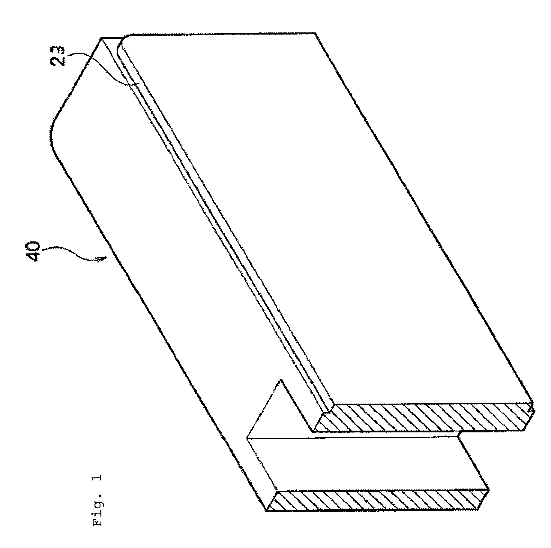
[0043]FIG. 1 shows a plate body adopted in the gate valve for vacuum in accordance with an embodiment of the present invention, and

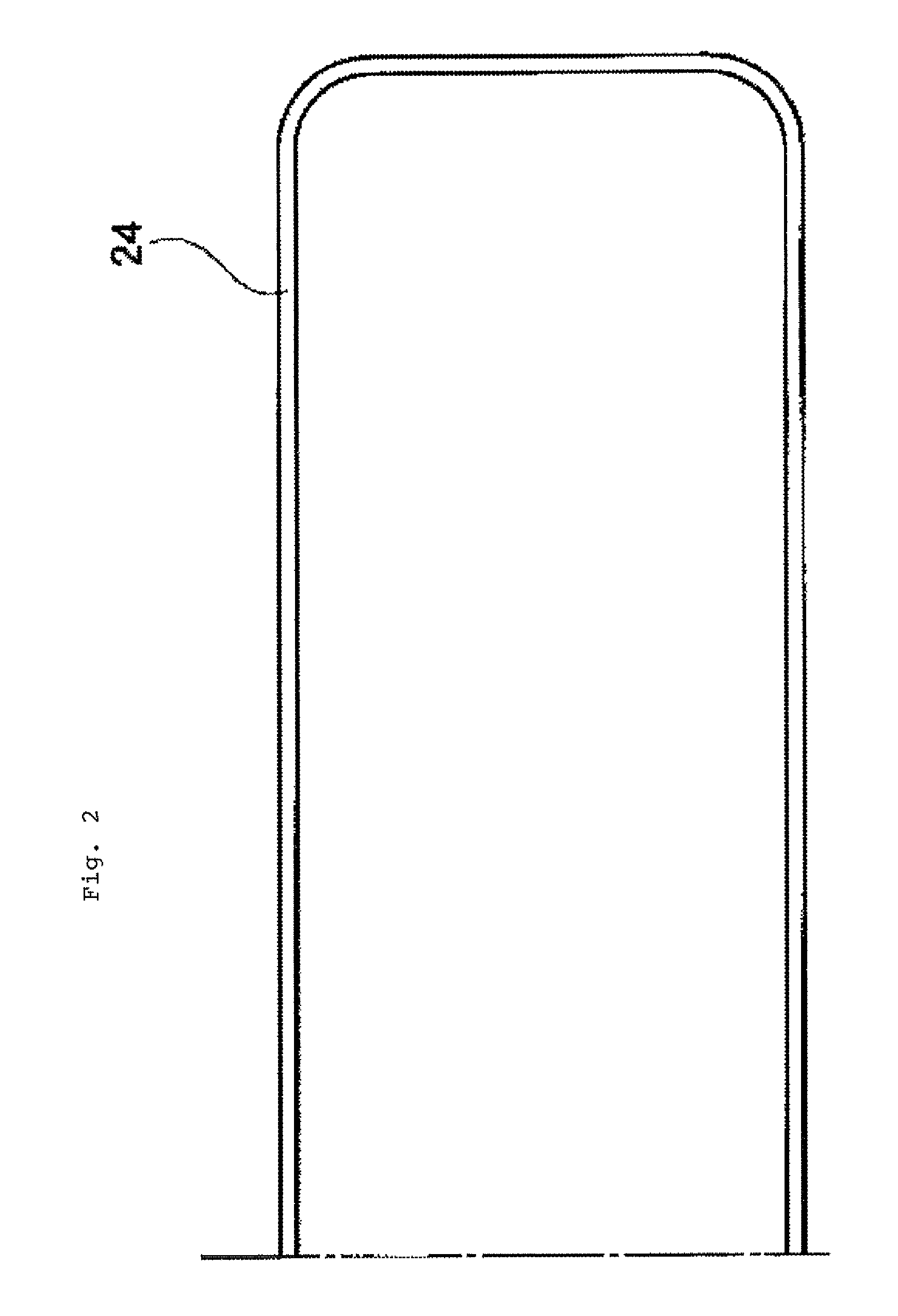
[0044]FIG. 2 is a front elevational view showing a seal member mounted on the plate body of FIG. 1.

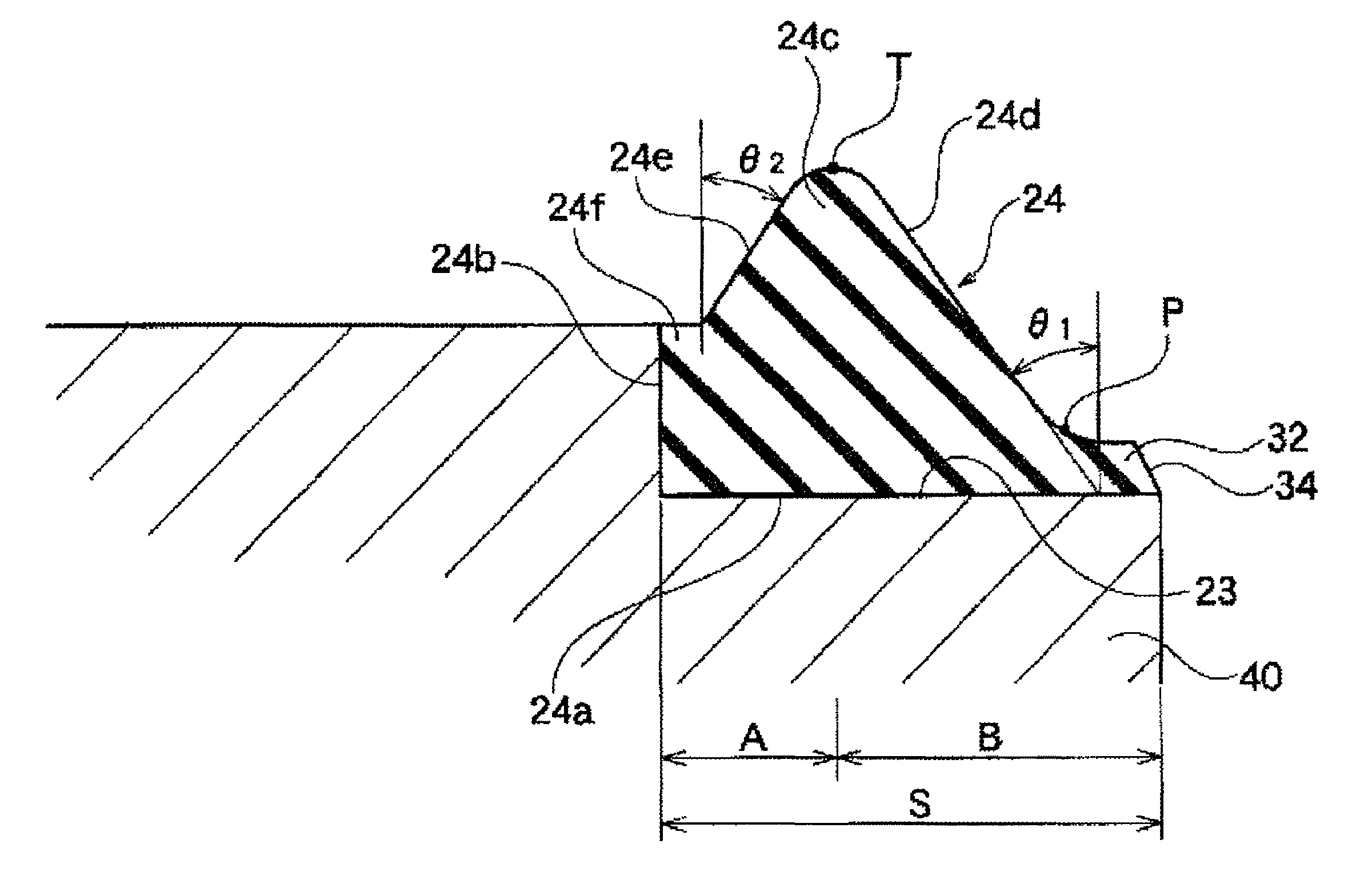
[0045]FIGS. 1 and 2 are corresponded to FIG. 6. More specifically, a plate body 40 shown in FIG. 1 is corresponded to a plate body 8 shown in FIG. 6 and is made of a metal such as aluminum. The plate body 40 is formed lengthwise in a horizontal direction corresponding to a plate body 8. A seal member 24 is in a band-like shape in a natural state, and is arranged in a circular pattern by being mounted in a seal member mounting groove 23 of the plate body 40.

[0046]As shown in an expanded view of FIG. 3, a seal member mounting groove 23 having a cross section in a generally L shape is formed on a peripheral edge of the plate body 40 shown in ...


PUM


Abstract

A gate valve for vacuum capable of preventing a seal member from being cracked or particles from being produced due to a stress concentration even if the seal member is repeatedly compressed in the state that the adhesive agent is separated from the open side of a seal member mounting groove and capable of suppressing particles from being produced due to the rub of the seal top part with the seal surface.

Description

TECHNICAL FIELD[0001]The present invention relates to a gate valve for vacuum being used for a semiconductor manufacturing apparatus or the like and to a seal member to be used for the gate valve for vacuum.BACKGROUND ART[0002]The work processing such as ion plating and plasma etching is carried out in a clean environment and in a high vacuum for a fabrication of a semiconductor such as a silicon wafer, a thin film, and liquid crystal.[0003]As a valve structure for opening and closing an open part that requires an high air-tightness and that a processed substance such as a silicon wafer can be easily transferred into and from, a bonded-type gate valve for vacuum is publicly known.[0004]For instance, the bonded-type gate valve for vacuum has advantages that a sealing performance is higher and a repeated opening and closing operation property is excellent as compared with a conventional seal apparatus in which a seal member is simply mounted in a dovetail groove formed in a plate body...

Claims


Application Information

Patent Timeline
Patent Type & Authority Patents(United States)
IPC IPC(8): F16K3/02
CPCF16K3/0227F16K51/02F16J15/10F16J15/16
Inventor TSUJI, KAZUAKI
Owner VALQUA LTD
Why Eureka
Try Eureka