Battery module

a battery module and battery technology, applied in the field of batteries, can solve the problems of reducing the number of connections conducted after fixing work, affecting so as to improve the ease of assembly, improve the cooling effect of cells, and improve the assembling

Active Publication Date: 2011-12-13
HITACHI VEHICLE ENERGY
View PDF12 Cites 14 Cited by
  • Summary
  • Abstract
  • Description
  • Claims
  • Application Information

AI Technical Summary

Benefits of technology

[0006]In view of these circumstances, an object of the present invention is to provide a battery module which is excellent in cooling easiness of cells and whose assembling easiness has been improved at a low cost.
[0008]Generally, in arrangement and fixation of a plurality of assembled batteries in a lower lid, when the lower lid has a box shape having a deep bottom, such a work must be conducted that the plurality of assembled batteries are inserted therein. Therefore, an inserting and fixing work itself becomes much troublesome and a connecting work conducted thereafter lowers due to interference of walls (the front face, the back face, the left side face, and the right side face) of the exterior case. On the contrary, when a plurality of assembled batteries are arranged and fixed on a plate-like lower lid, not only a inserting work but also a fixing work are simplified, but since it is thought that placing of the upper lid is the same as insertion in invisible state, safety in assembling work of the battery module reaching a high voltage may be blocked. In the present invention, the exterior case formed in an approximately hexahedral or cubic shape is constituted by connecting the lower lid with three faces of the front face, the bottom face, and the back face and the upper lid with three faces of the left side face, the upper face, and the right side face to each other as tradeoff between the above-described cases. Since the lower lid has the front face, the bottom face, and the rear face, the front face and the back face serve as walls. Therefore, arrangement and fixation of a plurality of assembled batteries means a work considerably similar to arrangement of assembled batteries on the plate-like lower lid corresponding to the latter case, so that workability is improved owing to opened space by utilizing the left side face and the right side face as working faces for the plurality of assembled batteries. Since the upper lid has three faces of the left side face, the upper face, and the right side face, two faces of the left and right side faces serve as walls, so that check with eyes can be performed from the front and back face directions when the upper lid should be fixed. Thus, safety can be improved like the former case. Further, since the upper lid and the lower lid each have three faces, cost reduction can be achieved as compared with the exterior case with the box structure having five faces corresponding to the former case.
[0009]In the present invention, when such a constitution is adopted that positive and negative electrode output line taking-out ports are provided at the front face of the exterior case, since the front face is provided on the lower lid. Therefore, the positive and negative electrode output line taking-out ports are disposed in the lower lid, so that erroneous wire connection can be prevented and safe electric connection can be performed by fixing positive and negative power lines before a plurality of assembled batteries are accommodated and fixed in the lower lid. When ventilation ports are provided in the front face and the back face of the exterior case, if ventilation passages communicating with the ventilation ports are formed in the lower lid in advance, formation of a cooling system is completed by only arranging a plurality of assembled batteries on the lower lid and connecting the upper lid to the lower lid, so that assembling easiness can be improved.
[0010]In the above aspect, when the lower lid and the upper lid are fixed to each other such that first flange portions extending from a bottom face portion of the lower lid laterally correspond to second flange portions extending from left and right side faces of the upper lid laterally, positioning of the upper lid and the lower lid is simplified owing to the first and second flange portions extending laterally so that workability is improved, and since flat faces are formed by the first and second flange portions, screw-fastening is facilitated. In this case, when a coupling portion between the lower lid and the upper lid directly contacts with a placement face of the exterior case, load exceeding force required for coupling of the lower lid and the upper lid is applied to the placement face when vibration or the like is applied thereto, there is a possibility that the coupling portion is broken. However, when the first flange portions are positioned above the bottom face of the lower lid, the coupling portion between the lower lid and the upper lid is positioned above the placement face of the exterior case, and a structure that the first flange portions do not contact with the placement face of the exterior case is obtained, so that breaking of the coupling portion due to vibration or the like is prevented and reliability of the coupling portion is improved. At this time, when end portions of the first flange portions are bent upwardly, rigidity is increased and structural strength is increased as compared with a flat end of the first flange portion, so that reduction in plate thickness and therefore decrease of the amount of material to be used can be achieved, and the weight of the lower lid and cost thereof can be reduced. Further, since the end portions are bent upwardly, positioning between the lower lid and the upper lid is facilitated when both the lids are coupled to each other, so that workability can be improved. When the end portions of the first flange portions have a waveform shape, rigidity to distortion such as bending is improved as compared with linear end portions. Further, when the second flanges are formed so as to conform to the wave shape of the end portion of the first flange portion, such a shape can be utilized for positioning at the coupling time of the lower lid and the upper lid, so that assembling easiness of the battery module can be improved. When end portions of the left side face, the upper face, and the right side face of the upper lid are drawn at the sides of the front face and the back face of the lower lid, structural strength is increased and the upper lid itself is reduced in distortion. Furthermore, reduction in plate thickness and decrease of the amount of material to be used can be achieved owing to rising of the strength so that weight and cost of the upper lid can be reduced.
[0011]When the assembled batteries are arranged and fixed between two frames whose sections have an approximate h-shape in section and which are opposed to each other in parallel with each other, since the frames have the approximate h-shaped sections, a plurality of assembled batteries can be fixed by flat faces with high section coefficient, which does not require a fixing member for each assembled battery. Therefore, weight reduction and space saving can be achieved and size variations of assembled batteries can be accommodated appropriately. When a group of assembled batteries is constituted by electrically connecting assembled batteries disposed and fixed between such frames, handling of the assembled batteries at an assembling step is facilitated, and when a plurality of such assembled battery groups are accommodated and fixed in parallel inside the exterior case, assembling easiness of the battery module can be considerably improved. At this time, the bottom faces of the assembled batteries are fixed by two approximate h-shaped frames, but when large impact is applied to the whole assembled battery group upwardly, respective assembled batteries may be vibrated individually in a fixed state only at the bottom faces of the assembled batteries. Therefore, when reinforcing plates with a approximate L-shape in section are arranged above the assembled battery groups so as to be parallel to the frames for arranging and fixing the assembled battery groups, a structure where large impacts in a vertical direction and in a horizontal direction can be endured can be obtained by the approximately L-shaped reinforcing plate which is stronger in lateral impact than a simple flat plate.

Problems solved by technology

Therefore, an inserting and fixing work itself becomes much troublesome and a connecting work conducted thereafter lowers due to interference of walls (the front face, the back face, the left side face, and the right side face) of the exterior case.

Method used


Image

  • Battery module
  • Battery module
  • Battery module

Examples


first embodiment

[0029]A first embodiment where the present invention has been applied to a battery module for an electric vehicle will be explained below with reference to the drawings.

[0030]Constitution

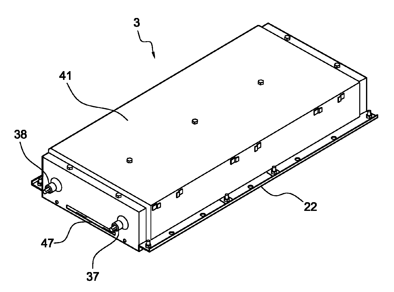
[0031]As shown in FIG. 1, a battery module 3 of this embodiment is provided with an exterior case formed in an approximately hexahedral or cubic shape made from metal and composed of an upper lid 41 and a lower lid 22. A plurality of assembled battery units 2, each being composed of unit cells, are accommodated and fixed in the exterior case (see FIG. 11).

[0032]

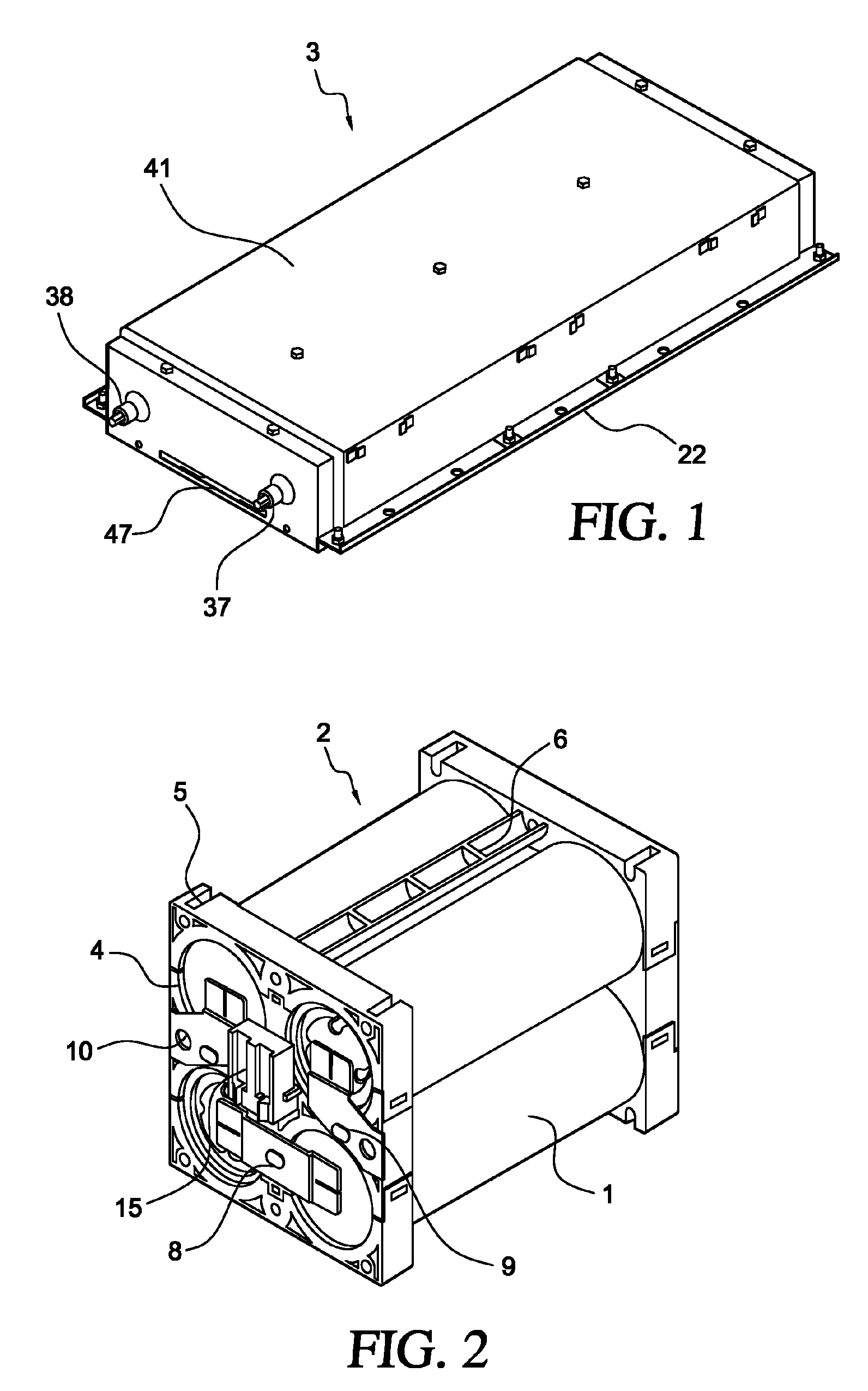
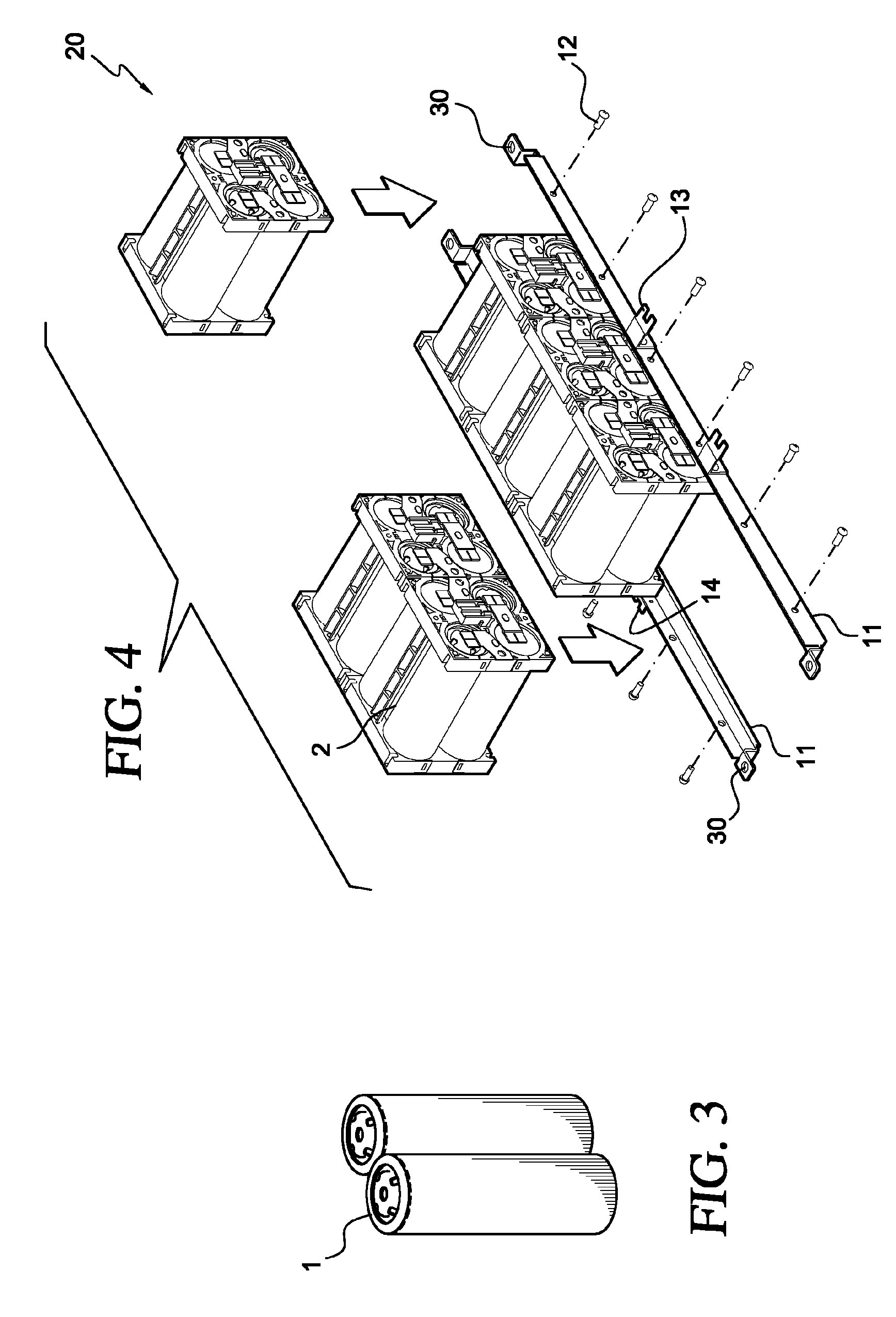
[0033]In the assembled battery unit 2, as shown in FIG. 2, four unit cells 4 are arranged in two rows and two columns such that their polarities become alternate and they are connected in series. There are various shapes of unit cells, but a cylindrical lithium secondary cell formed by covering a main constituent material (active material) such as lithium manganese with a casing with high heat conductivity is used in this embodiment, as shown...

second embodiment

[0073]Next, a second embodiment where the present invention is applied to a battery power source apparatus for an electric vehicle or a motor vehicle will be explained. The battery power source apparatus according to the present invention is constituted by stacking two battery modules. In the present embodiment, same members as those in the first embodiment are attached with same reference numerals in the first embodiment and explanation thereof is omitted. Only portions in the present embodiment different from the first embodiment will be explained in the following.

[0074]As shown in FIG. 14 and FIG. 15, a battery power source apparatus 100 according to the embodiment has a base stand 55 on which the battery module 3 is mounted. Since the lower lid flange portions 39 are positioned above the bottom face of the lower lid 22, arrangement and fixation on the mounting side (a vehicle side) can be performed easily. If stud bolts or welded nuts are mounted on flanges on the mounting side,...


PUM

PropertyMeasurementUnit
velocityaaaaaaaaaa
bearing forceaaaaaaaaaa
polaritiesaaaaaaaaaa

Abstract

The present invention provides to a battery module which is excellent in cooling performance of a battery and is improved in assembling easiness at low cast. A battery module 3 accommodates assembled battery blocks 20 arranged in series in an exterior case formed in an approximately hexahedral shape in parallel, each assembled battery block 20 including six assembled battery units electrically connected in series and each assembled battery unit including four cylindrical unit cells arrange such that their polarities are alternating. An exterior case is formed by connecting a lower lid 22 having a front face, a bottom face, and a back face and an upper lid 41 having a left side face, an upper face, and a right side face. End portions of the left side face, the upper face, and the right side face of the upper lid are drawn at the sides of the front face and the back face of the lower lid.

Description

FIELD OF THE INVENTION[0001]The present invention relates to a battery module, and in particular to a battery module where a plurality of assembled batteries are accommodated in an exterior case formed in an approximately hexahedral or cubic shape, each assembled battery including a plurality of cylindrical unit cells electrically connected such that polarities thereof are alternating.DESCRIPTION OF THE RELATED ART[0002]Conventionally, a high performance secondary cell or battery such as a nickel hydride battery or a lithium battery is used as a mobile power source for an electric vehicle or the like. In such a secondary battery, it is necessary to detect voltages of individual unit cells therein for grasping a battery performance of the secondary battery. Further, since the number of cells to be used increases, an assembling work for a battery power source apparatus (a battery module) is complicated. Furthermore, since an amount of heat generation during use of the module is relati...

Claims


Application Information

Patent Timeline
Patent Type & Authority Patents(United States)
IPC IPC(8): H01M4/48H01M10/60H01M10/613H01M10/617H01M10/625H01M10/643H01M10/652H01M10/6556H01M10/6563H01M10/6566H01M50/213H01M50/224H01M50/262H01M50/276H01M50/296H01M50/507H01M50/51H01M50/516H01M50/522H01M50/569H05K5/02
CPCH01M2/1077H01M2/206H01M10/5073H01M10/503H01M10/5036H01M10/5038H01M10/5067H01M10/5004Y02T10/7011H01M10/052H01M10/345H01M10/6563H01M10/652H01M10/643H01M10/6566H01M10/651H01M10/613Y02E60/10H01M50/507H01M50/522H01M50/224H01M50/213H01M50/276H01M50/516H01M50/51H01M50/296H01M50/569H01M50/262
Inventor GOTO, TAKEYUKIONUKI, TOSHIAKIAIBA, TUNEMIIKEDA, KOUTAROU
Owner HITACHI VEHICLE ENERGY
Why Eureka
Try Eureka