Control apparatus for spark-ignition engine

a control apparatus and spark ignition technology, applied in the direction of electrical control, process and machine control, instruments, etc., can solve the problems of ineffective use of techniques, exhaust gas worsening, knocking, etc., and achieve the effect of decreasing thermal efficiency

Active Publication Date: 2011-12-13
HITACHI ASTEMO LTD
View PDF13 Cites 7 Cited by
  • Summary
  • Abstract
  • Description
  • Claims
  • Application Information

AI Technical Summary

Benefits of technology

[0011]One of major causes of the lack of uniformity in the temperature inside the combustion chamber is the existence of internal EGR (Exhaust Gas Recirculation), that is, high temperature residual gas. It is extremely difficult to completely mix the internal EGR with air to homogenize a mixture gas existing in the combustion chamber during a period of time from an intake stroke up to a compression stroke. Therefore, a hot spot is generated in an end gas unit at the time of flame propagation, which causes knocking to occur. Specifically, in order to improve the antiknock property of a spark ignition engine, it is important to eliminate a hot spot caused by the internal EGR.
[0030]According to the present invention, knocking at the time of high-load operation can be avoided without using a residual-gas suction unit, or the like, without causing an exhaust gas to deteriorate due to injection in a compression stroke, and without decreasing the thermal efficiency.

Problems solved by technology

However, because the technique disclosed in JP-A-2006-77711 requires the residual-gas suction unit, this technique is not practically used.
This causes an exhaust gas to become worse.
The temperature and pressure of part of an unburnt mixture gas (end gas) increase during flame propagation and the part of the unburnt mixture gas is autoignited, as a result of which a spark-ignition engine undesirably generates knocking.
Therefore, when the temperature inside the combustion chamber is not uniform, knocking will occur at a location at which the temperature is higher (hot spot).
One of major causes of the lack of uniformity in the temperature inside the combustion chamber is the existence of internal EGR (Exhaust Gas Recirculation), that is, high temperature residual gas.
It is extremely difficult to completely mix the internal EGR with air to homogenize a mixture gas existing in the combustion chamber during a period of time from an intake stroke up to a compression stroke.
Therefore, a hot spot is generated in an end gas unit at the time of flame propagation, which causes knocking to occur.

Method used


Image

  • Control apparatus for spark-ignition engine
  • Control apparatus for spark-ignition engine
  • Control apparatus for spark-ignition engine

Examples


first embodiment

[0049]The configuration of a control apparatus for a spark-ignition engine according to the present invention, and the operation thereof, will be described below with reference to FIGS. 1 through 7.

[0050]First of all, the configuration of a system in which the control apparatus for the spark-ignition engine according to this embodiment is applied to an automobile gasoline engine will be described with reference to FIG. 1.

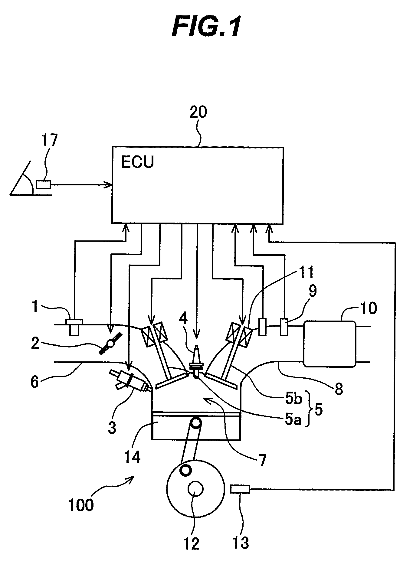
[0051]FIG. 1 is a diagram illustrating the configuration of the system in which the control apparatus for the spark-ignition engine according to the first embodiment of the present invention is applied to the automobile gasoline engine.

[0052]An engine 100 is an automobile gasoline engine that performs spark-ignition combustion. The engine 100 includes an intake pipe 6 having an airflow sensor 1 for measuring the amount of intake air and an electronic control throttle 2 for adjusting an intake flow rate. Each of the airflow sensor 1 and the electronic control throttl...

second embodiment

[0094]Next, the configuration of a control apparatus for a spark-ignition engine according to the present invention, and the operation thereof, will be described with reference to FIGS. 8, 9. The configuration of a system in which the control apparatus for the spark-ignition engine according to this embodiment is applied to an automobile gasoline engine is similar to that shown in FIG. 1. The control apparatus for the spark-ignition engine according to this embodiment is configured in a manner similar to that shown in FIG. 2. A high-load operation area used by the control apparatus for the spark-ignition engine according to this embodiment is similar to that shown in FIG. 3. Fuel injection control performed by the control apparatus for the spark-ignition engine according to this embodiment is similar to that shown in FIG. 4.

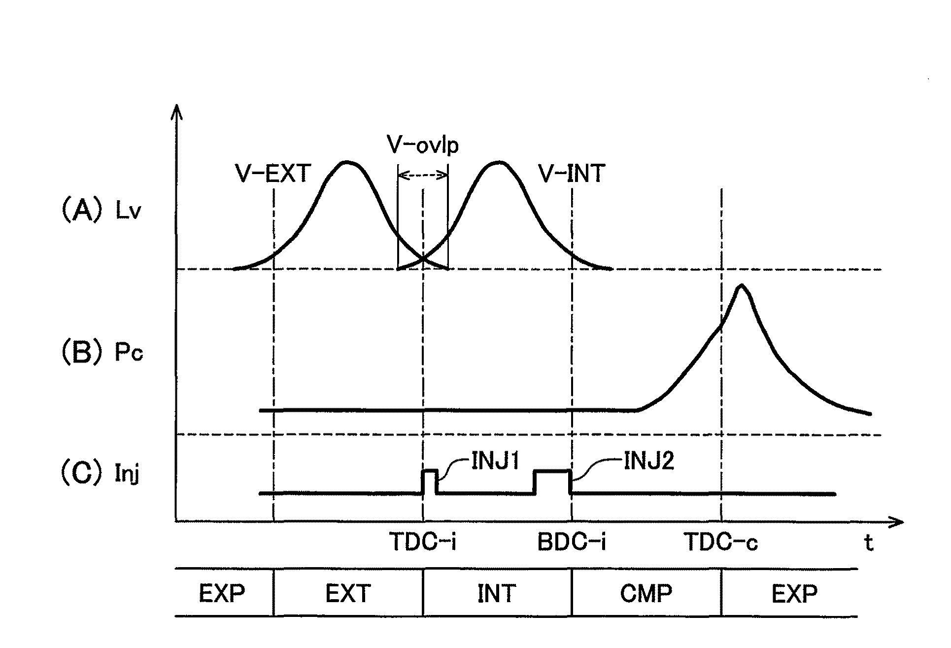
[0095]FIGS. 8A through 8C are timing charts each illustrating the fuel injection control for the high-load operation area performed by the control apparatus for ...

third embodiment

[0107]Next, the configuration of a control apparatus for a spark-ignition engine according to the present invention, and the operation thereof, will be described with reference to FIGS. 10 through 12. The configuration of a system in which the control apparatus for the spark-ignition engine according to this embodiment is applied to an automobile gasoline engine is similar to that shown in FIG. 1. The control apparatus for the spark-ignition engine according to this embodiment is configured in a manner similar to that shown in FIG. 2. A high-load operation area used by the control apparatus for the spark-ignition engine according to this embodiment is similar to that shown in FIG. 3.

[0108]FIG. 10 is a flowchart illustrating how the fuel injection is controlled by the control apparatus for the spark-ignition engine according to the third embodiment of the present invention. FIGS. 11A through 11C are timing charts each illustrating the fuel injection control for the high-load operatio...


PUM


Abstract

Disclosed herein is a control apparatus for a spark-ignition engine that is capable of avoiding knocking at the time of high-load operation. With this control apparatus, a residual-gas suction unit or the like is not used, an exhaust gas does not deteriorate due to injection in a compression stroke, and a thermal efficiency also does not decrease. An engine control apparatus (ECU) 20 is used for the control of a direct-injection type spark-ignition engine. During the high-load operation of the spark-ignition engine, the ECU 20 injects fuel a plurality of times. In addition, the ECU performs first fuel injection toward internal EGR that exists in a combustion chamber of the spark-ignition engine.

Description

BACKGROUND OF THE INVENTION[0001]1. Field of the Invention[0002]The present invention relates to a control apparatus for a spark-ignition engine, and more particularly to a control apparatus that is suitable for achieving a high compression ratio of a direct injection-type spark-ignition engine and the miniaturization thereof.[0003]2. Description of the Related Art[0004]For improvement in the fuel consumption of a spark-ignition engine used for an automobile or the like, the achievement of a high compression ratio of the engine and the miniaturization (downsizing) of the engine are attracting increasing attention. The fuel consumption of engines can be improved by achieving a high compression ratio to enhance the theoretical thermal efficiency, and by combining supercharging with downsizing to reduce the pumping loss and friction. However, since these engines are subjected to high temperature and high pressure inside a combustion chamber during a compression-expansion stroke in comp...

Claims


Application Information

Patent Timeline
Patent Type & Authority Patents(United States)
IPC IPC(8): F02B5/02
CPCF02D13/0265F02D35/027F02D37/02F02D41/006F02D41/402F02D13/0215F02D41/401F02D2041/001Y02T10/44Y02T10/47Y02T10/18Y02T10/12Y02T10/40
Inventor KUMANO, KENGOYAMAOKA, SHIROKAKUYA, HIROMUSUKEGAWA, YOSHIHIRO
Owner HITACHI ASTEMO LTD
Why Eureka
Try Eureka