Cooling apparatus with thermally conductive porous material and jet impingement nozzle(s) extending therein

a technology of thermally conductive porous materials and cooling apparatuses, which is applied in the direction of electrical apparatus casings/cabinets/drawers, cables, power cables, etc., can solve the problems of increasing device temperatures, thermal runaway conditions, increasing power dissipation, and therefore heat production, and achieves the effect of facilitating the jet impingement of liquid coolant, and facilitating the boiling of liquid coolan

Active Publication Date: 2011-12-20
LENOVO GLOBAL TECH INT LTD
View PDF27 Cites 20 Cited by
  • Summary
  • Abstract
  • Description
  • Claims
  • Application Information

AI Technical Summary

Benefits of technology

[0004]In one aspect, the shortcomings of the prior art are overcome and additional advantages are provided through the provision of a cooling apparatus. The cooling apparatus includes a housing, a thermally conductive porous material coupled to a surface to be cooled, and a liquid coolant supply. The housing includes a supply manifold and a return manifold, wherein the return manifold is in fluid communication with an outlet that extends through the supply manifold, and the thermally conductive porous material comprises at least one cavity exposing a portion of the surface to be cooled. The liquid coolant supply includes a jet impingement structure, which includes at least one jet nozzle for directing liquid coolant towards the surface to be cooled. The at least one jet nozzle extends into the at least one cavity in the thermally conductive porous material coupled to the surface to be cooled, and facilitates jet impingement of the liquid coolant onto the surface to be cooled.
[0005]In another aspect, a cooled electronic device is provided which includes one or more heat-generating electronic devices coupled to or comprising a surface to be cooled, and a cooling apparatus for cooling the surface to be cooled, and thereby the heat-generating electronic device(s). The cooling apparatus includes a housing, a thermally conductive porous material coupled to the surface to be cooled, and a liquid coolant supply comprising a jet impingement structure. The housing includes a supply manifold and a return manifold, wherein the return manifold is in fluid communication with an outlet that extends through the supply manifold, and the thermally conductive porous material comprises at least one cavity exposing a portion of the surface to be cooled. The jet impingement structure includes at least one jet nozzle for directing liquid coolant onto the surface to be cooled, wherein the at least one jet nozzle extends into the at least one cavity in the thermally conductive porous material coupled to the surface to be cooled, and facilitates jet impingement of the liquid coolant onto the surface to be cooled. During operative cooling of the surface to be cooled, the thermally conductive porous material coupled to the surface to be cooled facilitates boiling of liquid coolant passing therethrough, and thus; cooling of the heat-generating electronic device(s).
[0006]In a further aspect, a method is provided for fabricating a cooling apparatus for cooling a heat-generating electronic device coupled to or comprising a surface to be cooled. The method includes: providing a housing including a supply manifold and a return manifold, wherein the return manifold is in communication with an outlet that extends through the supply manifold; providing a thermally conductive porous material with at least one cavity extending therethrough; bonding the thermally conductive porous material to the surface to be cooled, wherein a portion of the surface to be cooled is exposed by the at least one cavity extending through the thermally conductive porous material; and disposing, in spaced relation to the surface to be cooled, at least one jet nozzle of a jet impingement structure at least partially within the at least one cavity so as to facilitate jet impingement of the liquid coolant onto the surface to be cooled, wherein the thermally conductive porous material coupled to the surface to be cooled facilitates boiling of liquid coolant passing therethrough.

Problems solved by technology

This heat should be removed from the devices in order to maintain device junction temperatures within desirable limits, with failure to remove heat effectively resulting in increased device temperatures, potentially leading to thermal runaway conditions.
First, power dissipation, and therefore heat production, increases as device operating frequencies increase.
Further, as more and more devices are packed onto a single chip, heat flux (Watts / cm2) increases, resulting in the need to remove more power from a given size chip or module.
These trends have combined to create applications where it is no longer desirable to remove heat from modern devices solely by traditional air cooling methods, such as by using air cooled heat sinks with heat pipes or vapor chambers.
Such air cooling techniques are inherently limited in their ability to extract heat from an electronic device with high power density.
Water-based coolants, however, must be kept from physical contact with electronic devices and interconnects, since corrosion and electrical short circuit problems are otherwise likely to result.

Method used


Image

  • Cooling apparatus with thermally conductive porous material and jet impingement nozzle(s) extending therein
  • Cooling apparatus with thermally conductive porous material and jet impingement nozzle(s) extending therein
  • Cooling apparatus with thermally conductive porous material and jet impingement nozzle(s) extending therein

Examples


Embodiment Construction

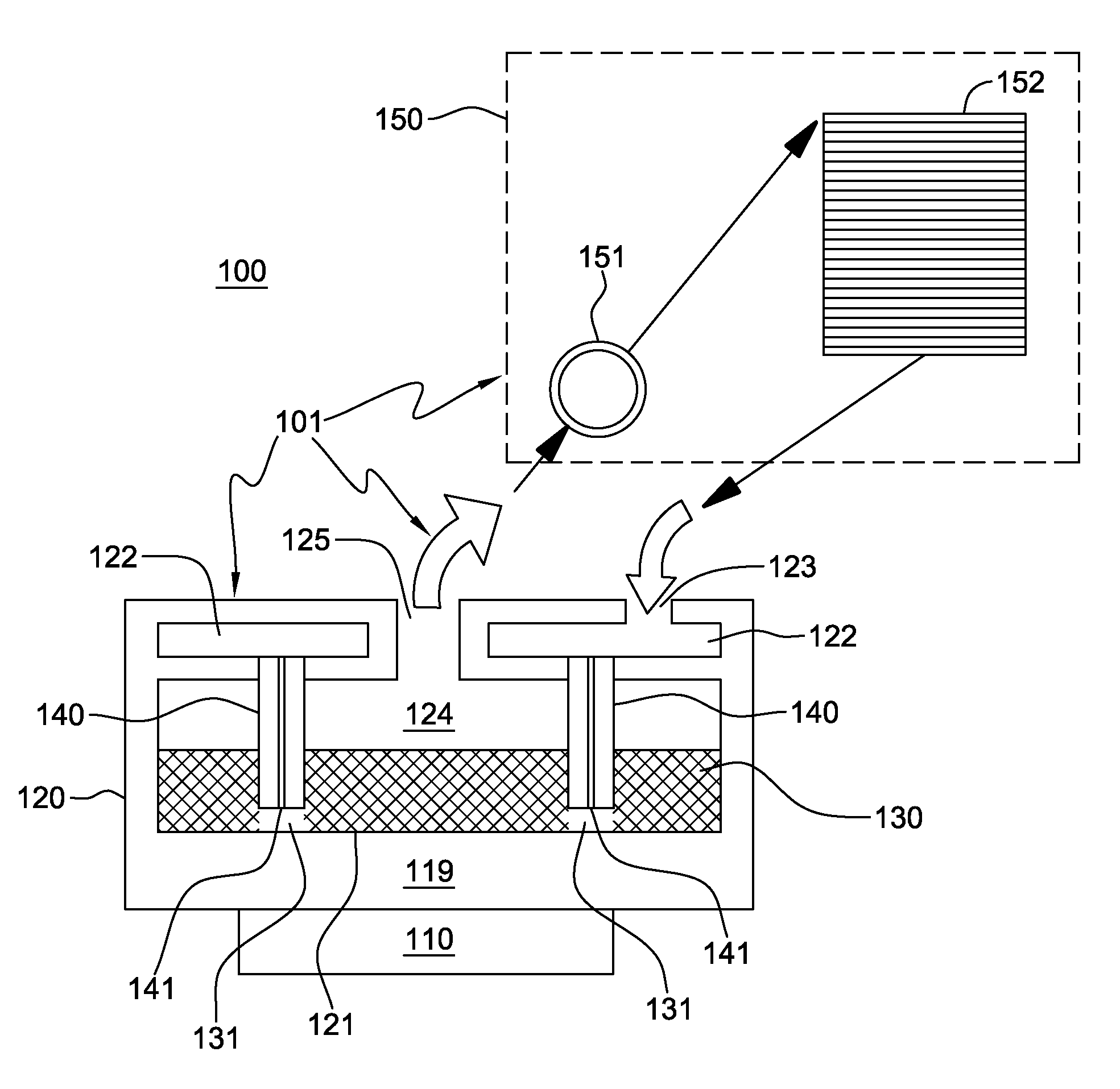
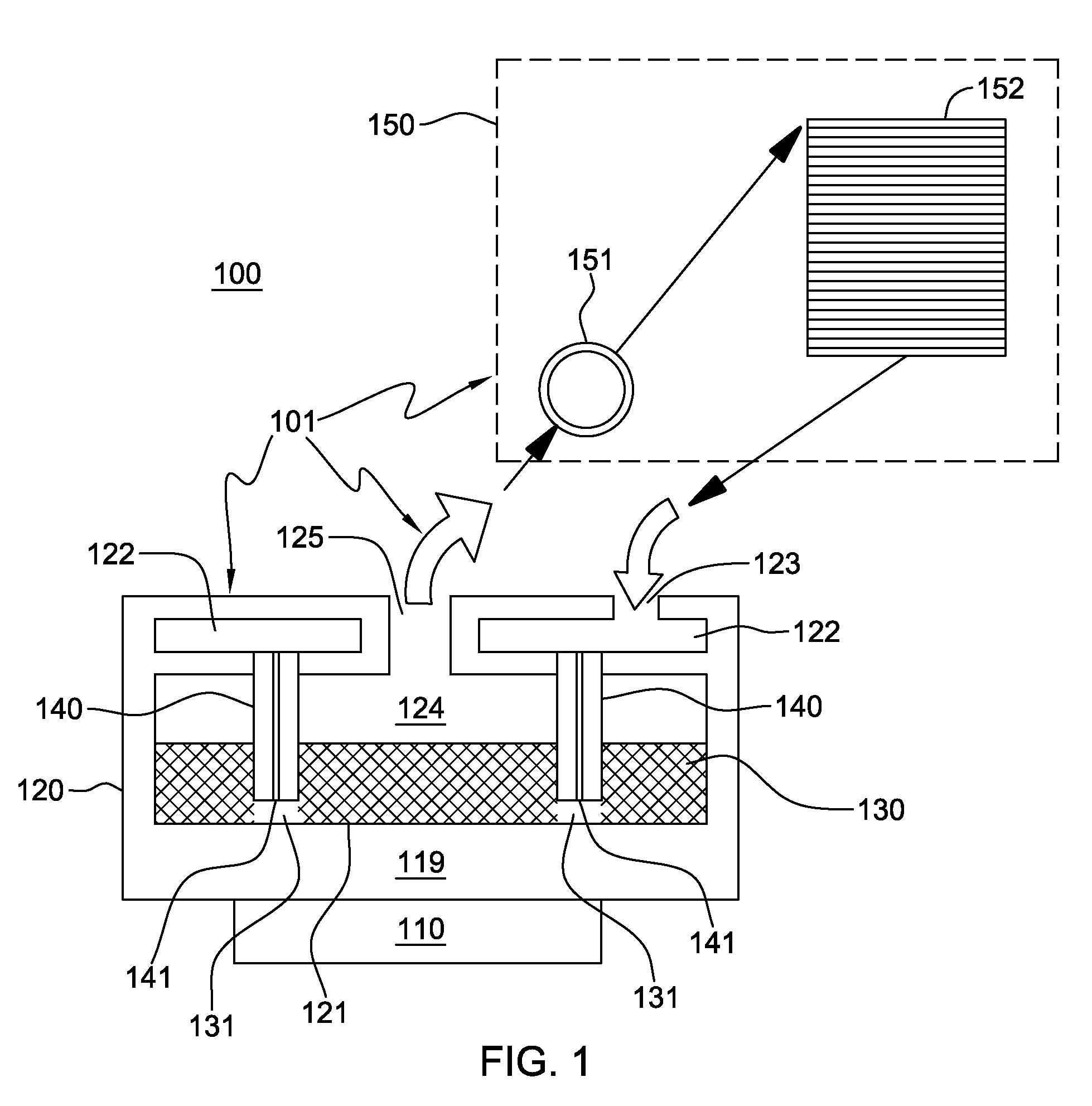
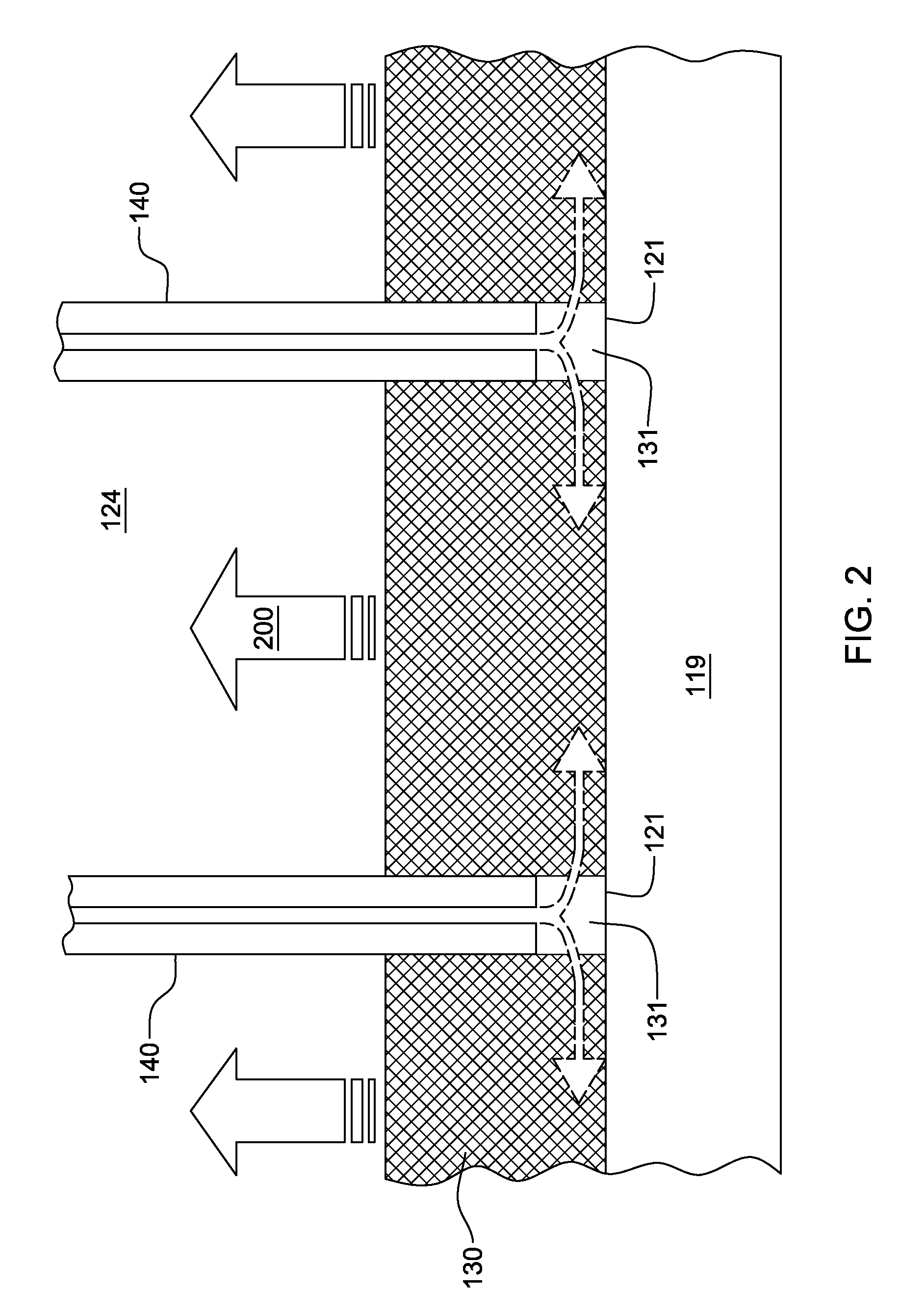
[0016]Generally stated, provided herein are cooling apparatuses, cooled electronic devices and methods of fabrication thereof which comprise a thermally conductive porous material bonded to a surface to be cooled and one or more jet nozzles extending into the thermally conductive porous material for directing liquid coolant onto the surface to be cooled. The surface to be cooled is a substantially planar main surface of a thermally conductive base, which comprises part of (or is coupled to) the electronic device to be cooled. The phrase “cooled electronic device” is used herein to include the heat-generating electronic device to be cooled with the cooling apparatus coupled thereto. In various embodiments, the cooling apparatus may include a vapor-compression heat exchange system or a pumped coolant system.

[0017]“Vapor-compression heat exchange system” means any heat exchange mechanism of the liquid coolant supply characterized as described herein through which refrigerant can circul...


PUM

PropertyMeasurementUnit
thermally conductiveaaaaaaaaaa
porosityaaaaaaaaaa
conductiveaaaaaaaaaa

Abstract

A cooling apparatus and method of fabrication are provided for facilitating cooling of an electronic device. The cooling apparatus includes a thermally conductive porous material and a liquid coolant supply. The thermally conductive porous material (such as metal foam material) is coupled to a surface of the electronic device to be cooled, or a structure coupled to the electronic device. The liquid coolant supply includes a jet impingement structure, which includes one or more jet nozzles for directing liquid coolant onto the surface to be cooled. The jet nozzle(s) extends into the thermally conductive porous material, and facilitates delivery of liquid coolant onto the surface to be cooled. The thermally conductive porous material is in thermal contact with the surface to be cooled and facilitates cooling of the electronic device by boiling of the liquid coolant passing through the porous material.

Description

BACKGROUND[0001]The present invention relates to heat transfer mechanisms, and more particularly, to cooling apparatuses, cooled electronic devices and methods of fabrication thereof for removing heat generated by one or more electronic devices. Still more particularly, the present invention relates to cooling apparatuses and methods of cooling a thermally conductive surface comprising part of or coupled to the electronic device to be cooled.[0002]As is known, operating electronic devices produce heat. This heat should be removed from the devices in order to maintain device junction temperatures within desirable limits, with failure to remove heat effectively resulting in increased device temperatures, potentially leading to thermal runaway conditions. Several trends in the electronics industry have combined to increase the importance of thermal management, including heat removal for electronic devices, including technologies where thermal management has traditionally been less of a...

Claims


Application Information

Patent Timeline
Patent Type & Authority Patents(United States)
IPC IPC(8): H05K7/20H01L23/34F28F7/00
CPCH01L23/4735F28D15/0266F28F13/187Y10T29/4935H01L2924/0002H01L2924/00
Inventor CAMPBELL, LEVI A.CHU, RICHARD C.ELLSWORTH, JR., MICHAEL J.IYENGAR, MADHUSUDAN K.SIMONS, ROBERT E.
Owner LENOVO GLOBAL TECH INT LTD
Why Eureka
Try Eureka