Water-cooled communication chassis

a communication chassis and water-cooled technology, applied in the direction of electrical apparatus casings/cabinets/drawers, power cables, cables, etc., can solve the problems of low heat conductivity of metal communication chassis, high temperature, and heat produced by electronic devices during operation thereof, so as to improve heat dissipation efficiency and quick circulation

Inactive Publication Date: 2011-12-20
ASIA VITAL COMPONENTS SHENZHEN CO LTD
View PDF12 Cites 17 Cited by
  • Summary
  • Abstract
  • Description
  • Claims
  • Application Information

AI Technical Summary

Benefits of technology

[0008]A primary object of the present invention is to provide a water-cooled communication chassis that includes a water cooling unit capable of driving a cooling fluid to quickly circulate in between the water cooling unit and a first water pipe system provided on a chassis body of the communication chassis, so that heat produced in the chassis body can be carried away therefrom at upgraded heat dissipating efficiency through the circulating cooling fluid.
[0009]Another object of the present invention is to provide a water-cooled communication chassis that ensures stable communication signal quality.
[0010]A further object of the present invention is to provide a water-cooled communication chassis that has increased service life.
[0011]To achieve the above and other objects, the water-cooled communication chassis according to a preferred embodiment of the present invention includes a chassis body and a water cooling unit. The chassis body includes at least one heat receiving portion, at least one heat dissipation portion, and at least one first water pipe system. The first water pipe system has a front part extended through the heat receiving portion and a rear part arranged on the heat dissipation portion, so that heat absorbed by the heat receiving portion is transferred via the first water pipe system to the heat dissipation portion and dissipated into ambient air. The water cooling unit communicates with the first water pipe system and drives a cooling fluid stored therein to circulate in between the first water pipe system and the water cooling unit, so that the heat absorbed by the heat receiving portion can be quickly and continuously carried away therefrom by the circulating cooling fluid. Therefore, by providing the water cooling unit and the first water pipe system to circulate the cooling fluid therein, the communication chassis can have excellent heat dissipating performance.

Problems solved by technology

However, being limited by the currently available casting techniques, the metal communication chassis usually has relatively low heat conductivity.
As a result, heat produced by the electronic devices during operation thereof tends to accumulate in and concentrate at some particular areas of the communication chassis.
The accumulated heat results in a relatively high temperature at these areas and cannot be easily dissipated from the closed communication chassis.
When the temperature exceeds the range that can be accepted by the electronic devices of the communication equipment, the reliability or service life of the communication equipment is seriously adversely affected.
That is, the temperature distribution in the conventional communication chassis is extremely uneven to largely reduce an overall heat dissipation performance of the whole communication chassis.
However, these solutions would inevitably result in a bulky and heavy communication chassis.
As a result, the heat in the communication chassis could not quickly diffuse outward and tends to damage the heat-producing elements 131 and interrupt computing process of the electronic communication equipment, resulting in poor communication signal quality.
According to the above description, the conventional communication chassis has the following disadvantages: (1) having poor heat dissipation effect; (2) easy to cause abnormal operation of the electronic communication equipment; (3) tending to cause poor communication signal quality; (4) tending to shorten the service life of the electronic communication equipment; and (5) having high damage rate.

Method used


Image

  • Water-cooled communication chassis
  • Water-cooled communication chassis
  • Water-cooled communication chassis

Examples


Embodiment Construction

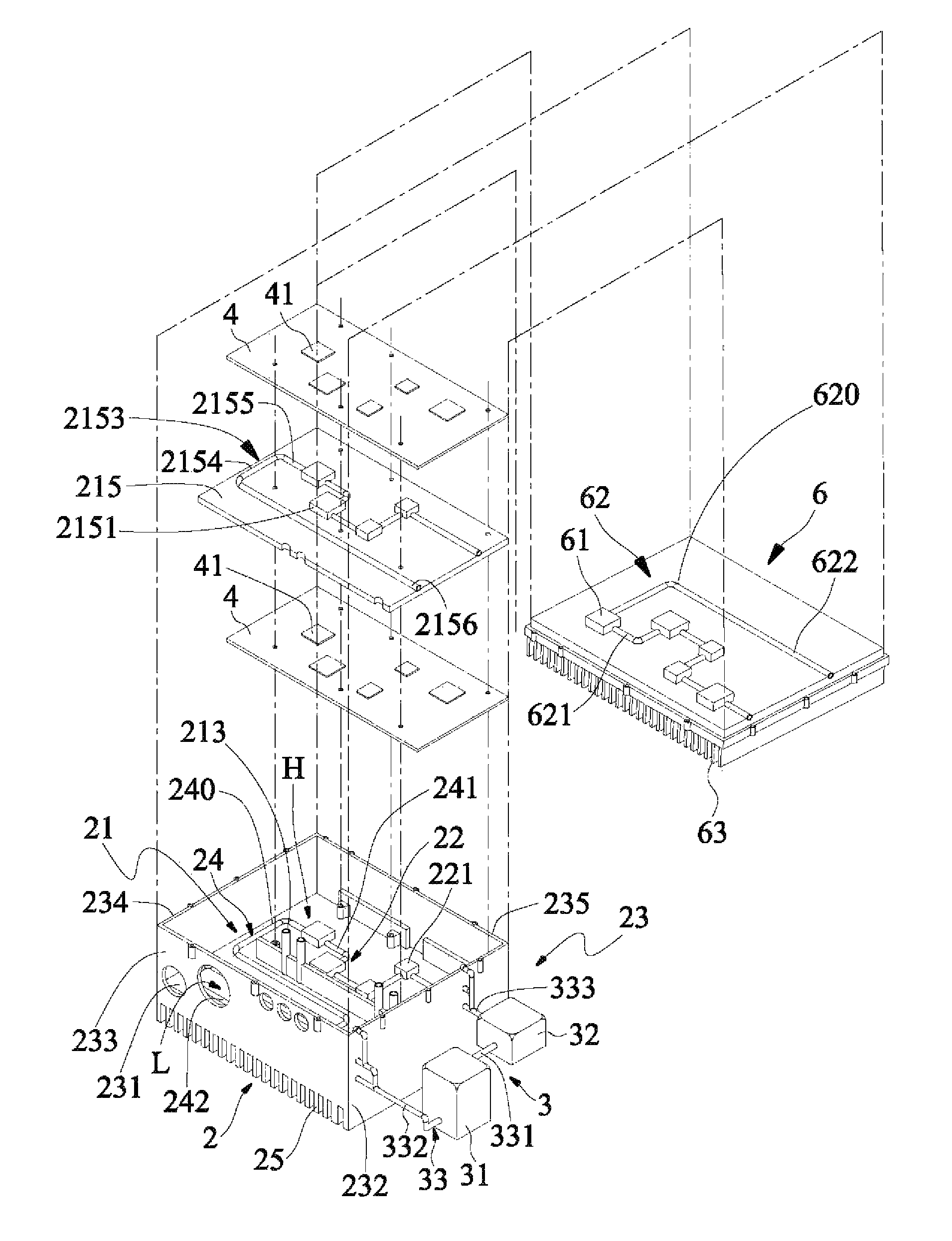
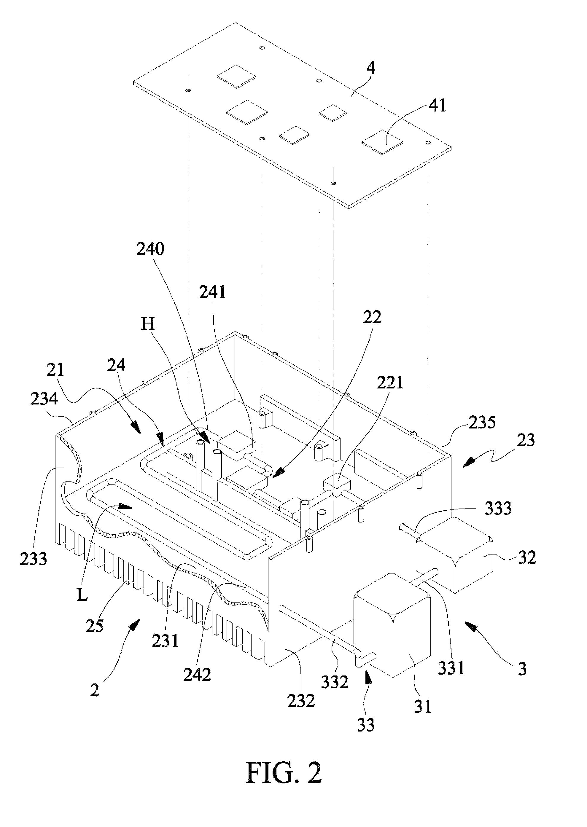
[0019]Please refer to FIGS. 2 to 6. A water-cooled communication chassis according to a preferred embodiment of the present invention includes a chassis body 2, at least one water-cooling unit 3, at least one machine board 4, and a cover 6. As can be seen from FIG. 2, which is an exploded perspective view showing the chassis body 2 and the water-cooling unit 3 of the water-cooled communication chassis of the present invention. The chassis body 2 includes at least one heat receiving portion 22, at least one heat dissipation portion 23, and at least one first water pipe system 24. The first water pipe system 24 has a front part extended through the heat receiving portion 22 and a rear part arranged on the heat dissipation portion 23. Heat absorbed by the heat receiving portion 22 is transferred via the first water pipe system 24 to the heat dissipation portion 23 and dissipated into ambient air. The water-cooling unit 3 is communicably connected to the first water pipe system 24, and ...


PUM


Abstract

A water-cooled communication chassis includes a chassis body and a water cooling unit. The chassis body includes at least one heat receiving portion, at least one heat dissipation portion, and at least one first water pipe system. The first water pipe system has a front part extended through the heat receiving portion and a rear part arranged on the heat dissipation portion, so that heat absorbed by the heat receiving portion is transferred via the first water pipe system to the heat dissipation portion and dissipated therefrom into ambient air. The water cooling unit communicates with the first water pipe system and drives a cooling fluid stored therein to circulate in between the first water pipe system and the water cooling unit, so that the heat absorbed by the heat receiving portion can be quickly and continuously carried away from the communication chassis by the circulating cooling fluid.

Description

FIELD OF THE INVENTION[0001]The present invention relates to a communication chassis, and more particularly to a water-cooled communication chassis that includes a water cooling unit capable of driving a cooling fluid to quickly circulate in between a water pipe system on a chassis body and the water cooling unit, so that the communication chassis has upgraded heat dissipating efficiency.BACKGROUND OF THE INVENTION[0002]It is known that electronic communication equipment is conventionally enclosed in a communication chassis. When the electronic devices of the communication equipment operate, heat is produced at the same time. The communication chassis is a closed enclosure generally made of a metal material through one-step cast-molding process. However, being limited by the currently available casting techniques, the metal communication chassis usually has relatively low heat conductivity. As a result, heat produced by the electronic devices during operation thereof tends to accumu...

Claims


Application Information

Patent Timeline
Patent Type & Authority Patents(United States)
IPC IPC(8): H05K7/20
CPCH05K7/20218
Inventor CHIU-MAO, HUANGCHANG-MOU, HUANG
Owner ASIA VITAL COMPONENTS SHENZHEN CO LTD
Why Eureka
Try Eureka