
Method for operating an injector

a technology of injector and injector body, which is applied in the direction of fuel injection apparatus, electric control, charge feed system, etc., can solve the problems of individual deviations in the fuel injection of each cylinder, inability to accurately measure a quantity of fuel to be injected, and inability to achieve accurate metering over the long term using the known methods, etc., to achieve the effect of increasing precision

Inactive Publication Date: 2011-12-27
ROBERT BOSCH GMBH
View PDF24 Cites 7 Cited by
  • Summary
  • Abstract
  • Description
  • Claims
  • Application Information

AI Technical Summary

Benefits of technology

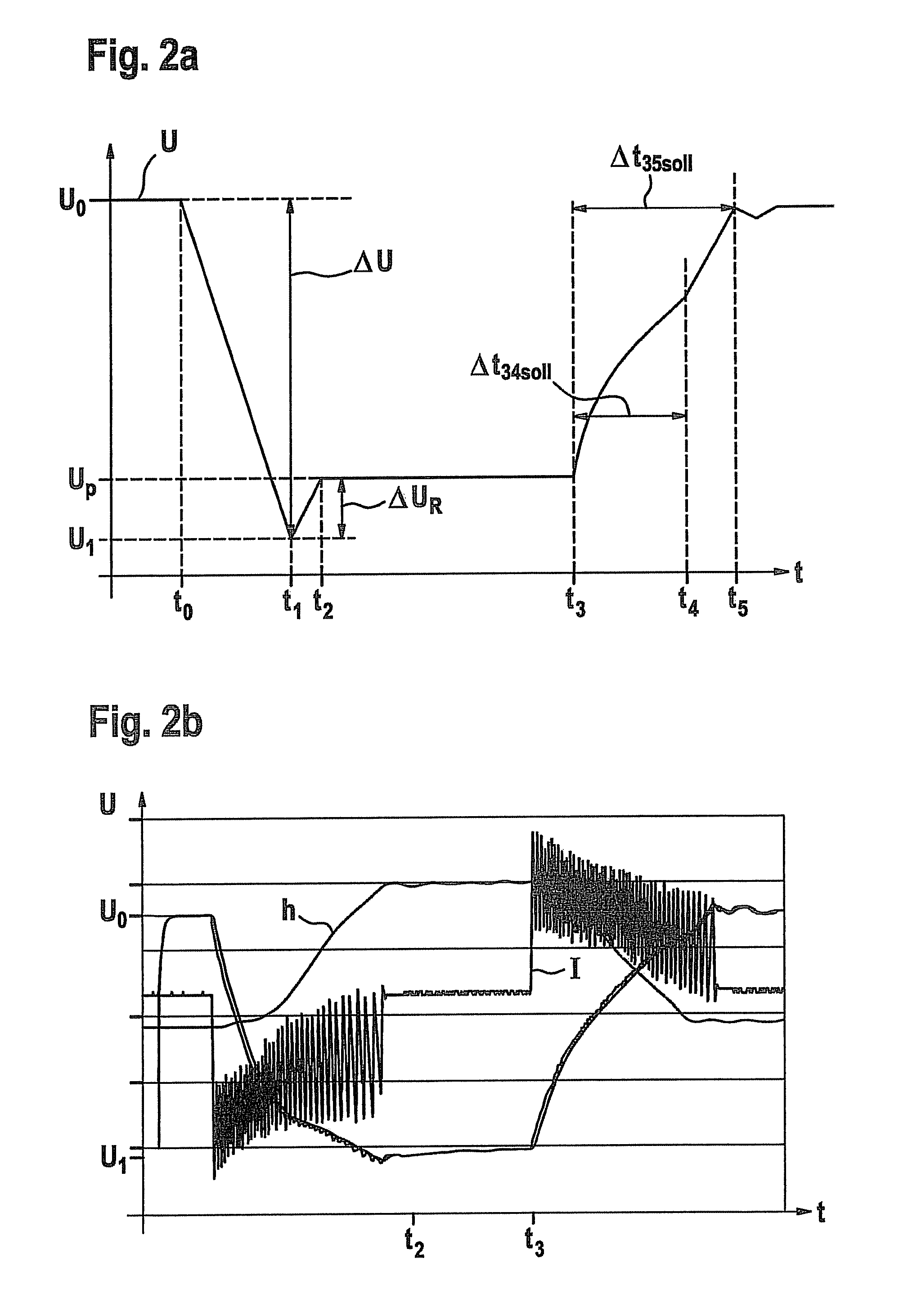
The present invention provides a method for accurately metering fluid injection in an injector by compensating for changes in the injector over time and age-related effects. The method takes into account the voltage swing of the actuator, which allows for a more precise setting of the desired operating state of the injector. The actuator is recharged with a predefined recharging time and a predefined recharging current, which ensures the same predefined recharging time for each recharging operation. The method also compensates for the feedback effect of the valve needle on the actuator, which allows for the adjustment of the valve needle's position and the quantity of fluid injected by it. Overall, the method provides a more accurate and reliable method for triggering the injector.

Problems solved by technology

However, because of aging effects in the piezoelectric actuator itself in particular as well as the mechanical and hydraulic components in the injector, there are changes in the corresponding electrical and / or mechanical parameters of the injector, so that accurate metering of a quantity of fuel to be injected, for example, is impossible over the long term using the known methods.
In addition to these aging effects, temperature fluctuations in the area of the injector in particular also cause a change in the electric capacitance of the piezoelectric actuator, resulting in additional inaccuracies in metering fuel or other fluids through the injector or in positioning the actuator in general.
In addition, part variations among various injectors, which are assigned to different cylinders of a certain internal combustion engine, for example, result in individual deviations in fuel injection for each cylinder, which are also unwanted.

Method used


Image

  • Method for operating an injector
  • Method for operating an injector
  • Method for operating an injector

Examples


Embodiment Construction

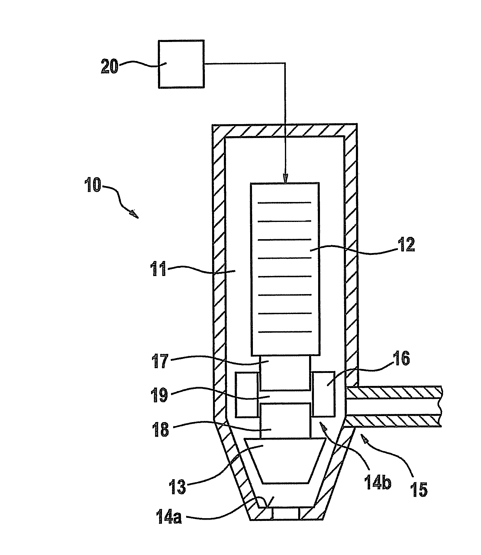
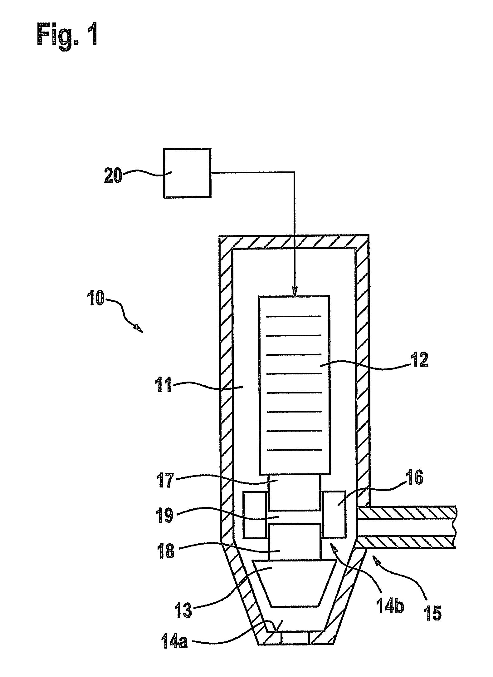
[0027]FIG. 1 shows an injector designed as a fuel injector 10 of an internal combustion engine in a motor vehicle equipped with a piezoelectric actuator 12. Piezoelectric actuator 12, as indicated by the arrow in FIG. 1, is triggered by a control unit 20. In addition, fuel injector 10 has a valve needle 13, which may sit on a valve seat 14a in the interior of the housing of fuel injector 10.

[0028]When valve needle 13 is lifted up from valve seat 14a, fuel injector 10 is opened and fuel is injected. This state is depicted in FIG. 1. This characterizes a completely opened state of fuel injector 10 in that valve needle 13 is in contact with a needle travel stop located in area 14b, but not shown in greater detail here, preventing further movement of valve needle 13 away from its seat 14a, i.e., toward actuator 12. When valve needle 13 sits on valve seat 14a, fuel injector 10 is closed. In other words, the entire vertical travel distance which valve needle 13 is able to travel in the il...


PUM


Abstract

A method is for operating an injector, in particular a fuel injector of an internal combustion engine in a motor vehicle, the injector having a piezoelectric actuator for driving a valve needle coupled, preferably hydraulically, to the actuator. Starting from a starting voltage corresponding to a first operating state of the injector, the actuator is recharged, i.e., charged or discharged, by a predefinable voltage swing to a target voltage corresponding to a second operating state of the injector.

Description

FIELD OF THE INVENTION[0001]The present invention relates to a method for operating an injector, in particular a fuel injector of an internal combustion engine in a motor vehicle, the injector having a piezoelectric actuator for driving a valve needle coupled, preferably hydraulically, to the actuator.BACKGROUND INFORMATION[0002]Injectors and methods of this type are known and usually include preselection of an actuator voltage to which the piezoelectric actuator is to be charged and / or recharged to move the valve needle of the injector to a desired position and / or to put the injector in a desired operating state. However, because of aging effects in the piezoelectric actuator itself in particular as well as the mechanical and hydraulic components in the injector, there are changes in the corresponding electrical and / or mechanical parameters of the injector, so that accurate metering of a quantity of fuel to be injected, for example, is impossible over the long term using the known ...

Claims


Application Information

Patent Timeline
Patent Type & Authority Patents(United States)
IPC IPC(8): F02M51/00
CPCF02D41/2096F02D2041/2051
Inventor LEHR, HANS-PETERTONNER, ERIK
Owner ROBERT BOSCH GMBH
Learn More