Closed loop dispensing system with mechanical venting means

a technology of mechanical venting and closed loop, which is applied in the direction of liquid dispensing, liquid flow controller, packaging, etc., can solve the problem of not intended summary

Active Publication Date: 2011-12-27
RD IND INC
View PDF39 Cites 28 Cited by
  • Summary
  • Abstract
  • Description
  • Claims
  • Application Information

AI Technical Summary

Benefits of technology

The vent pins permit air to pass through the associated vent openings when the valve and vent assembly is in its lower position. A spring is positioned between the lower wall and the disc of the valve and vent assembly which normally urges the valve and vent assembly to its upper position. The movement of the vent pin between its upper and lower positions prevents the accumulation of debris in the associated vent opening. The valve body and the tubular valve means extend upwardly through the central opening in the upper wall of the throat plug assembly.
A further object of the invention is to provide a closed loop dispensing system including a mechanical venting means which prevents the vent openings thereof from becoming plugged with debris.
Still another object of the invention is to provide a closed loop dispensing system with mechanical venting means which ensures that sufficient air will be vented into the interior of the liquid container as liquid is being drawn therefrom.
Still another object of the invention is to provide a closed loop dispensing system including a vent means which may function to relieve pressure within the liquid container during the shipment thereof.

Problems solved by technology

Moreover, this Summary is not intended for use as an aid in determining the scope of the claimed subject matter.

Method used


Image

  • Closed loop dispensing system with mechanical venting means
  • Closed loop dispensing system with mechanical venting means
  • Closed loop dispensing system with mechanical venting means

Examples


Embodiment Construction

Embodiments are described more fully below with reference to the accompanying figures, which form a part hereof and show, by way of illustration, specific exemplary embodiments. These embodiments are disclosed in sufficient detail to enable those skilled in the art to practice the invention. However, embodiments may be implemented in many different forms and should not be construed as being limited to the embodiments set forth herein. The following detailed description is, therefore, not to be taken in a limiting sense in that the scope of the present invention is defined only by the appended claims.

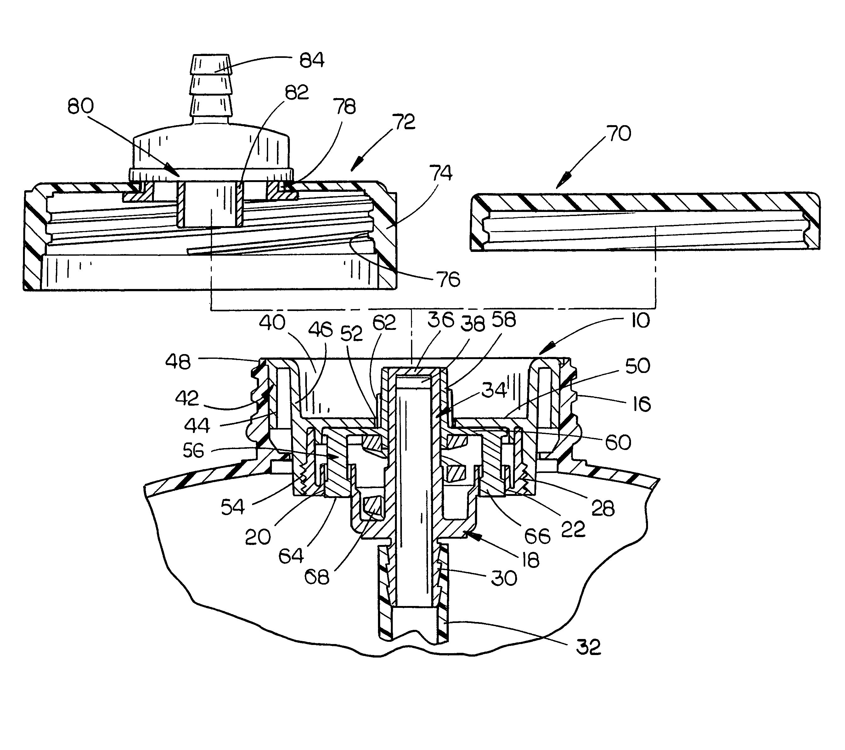
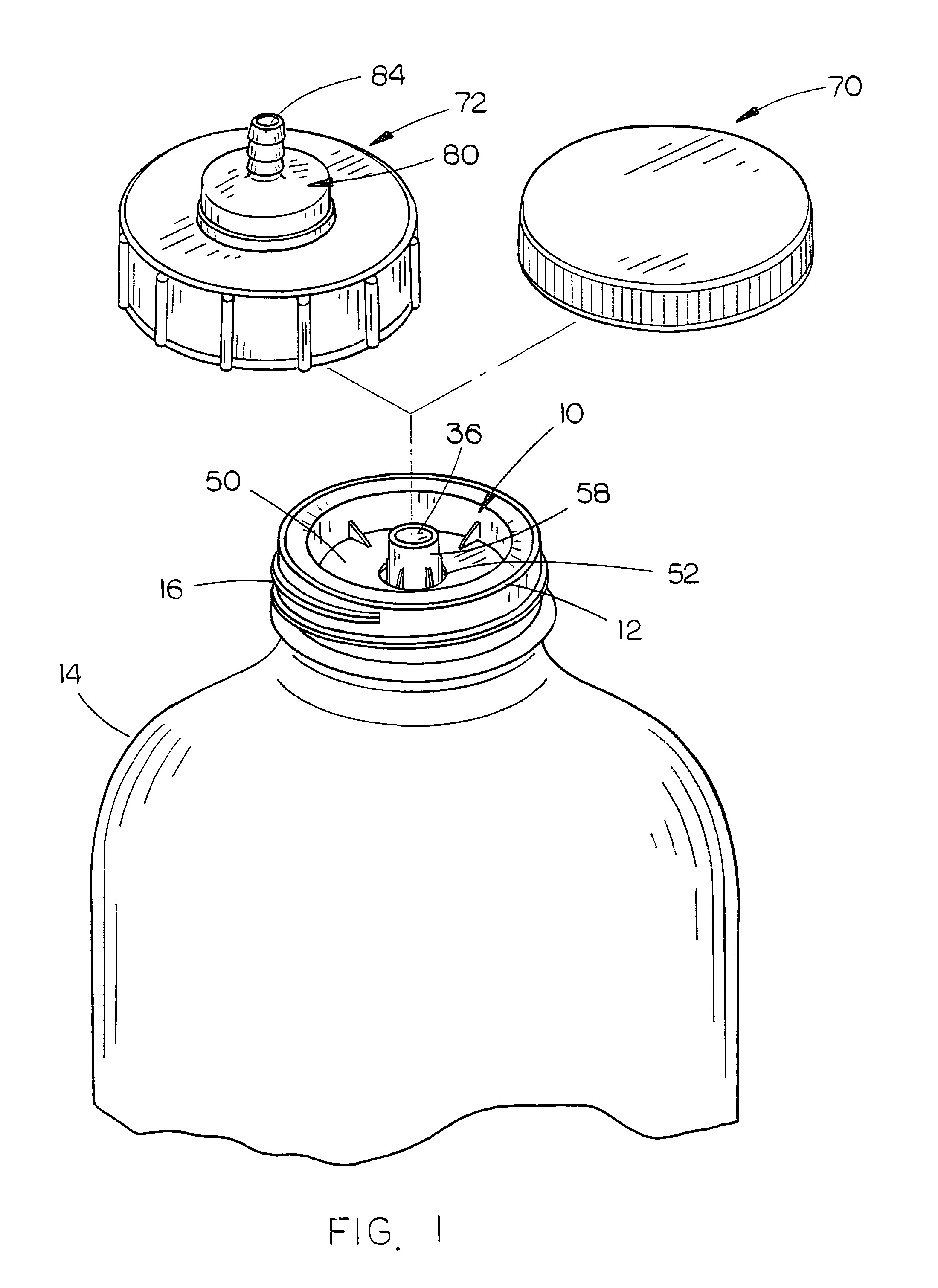
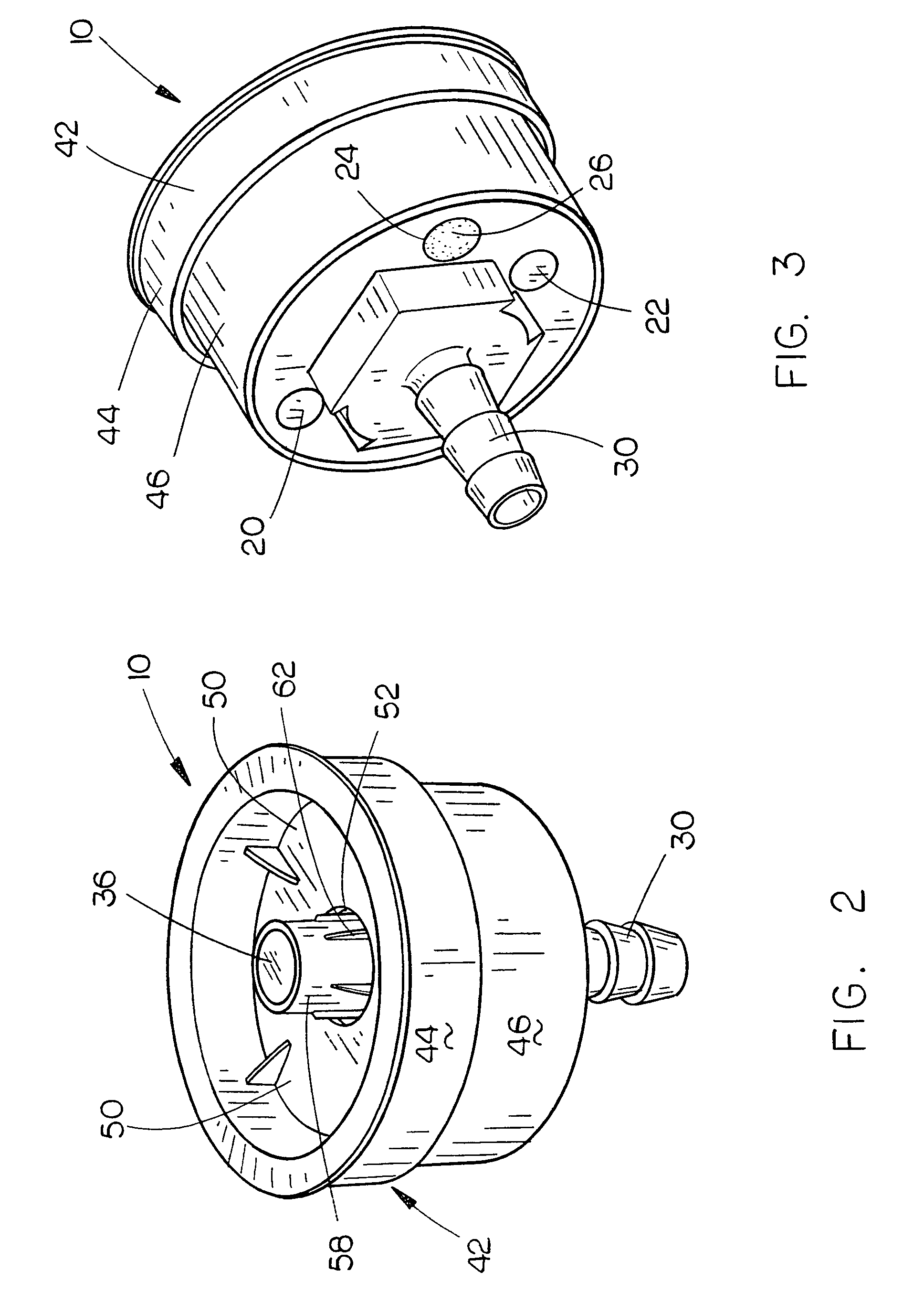
The numeral 10 refers to a throat plug assembly which is press-fitted into the throat or outlet opening 12 of a container 14 such as a bottle or the like. Preferably, throat 12 includes external threads 16. Assembly 10 includes an externally threaded disc member 18 having a pair of vent openings 20 and 22 formed therein as well as a vent opening 24 formed therein with the vent opening ha...


PUM


Abstract

A closed loop dispensing system including a mechanical venting assembly which ensures that sufficient air may enter the interior of the container as liquid is being drawn from the container. The mechanical venting assembly of this invention ensures that the vent openings associated therewith will not become plugged with debris.

Description

BACKGROUND OF THE INVENTION1. Field of the InventionThis invention relates to a closed loop dispensing system and more particularly to a dispensing system for dispensing corrosive liquid chemicals or dangerous medical liquid products which are typically drawn from a container such as a bottle or the like to a mixing machine or the like. Even more particularly, this invention relates to a closed loop dispensing system including a mechanical venting means for a throat plug assembly which is mounted in the throat of a liquid container.2. Description of the Related ArtCorrosive liquid chemicals and dangerous medical liquid products are typically contained in a container such as a bottle or the like and are frequently dispensed therefrom to a mixing machine. Normally, a cap is place on the bottle with a dip tube extending therefrom downwardly into the interior of the bottle for drawing the liquid upwardly thereinto. Normally, a dispensing tube extends from the cap from a mixing machine o...

Claims


Application Information

Patent Timeline
Patent Type & Authority Patents(United States)
IPC IPC(8): B67D3/00
CPCB65D47/283B65D47/32
Inventor LAIBLE, RODNEY
Owner RD IND INC
Why Eureka
Try Eureka