Electrical connector and molding method thereof

a technology of electrical connectors and connectors, applied in the direction of coupling device connections, coupling protective earth/shielding arrangements, electrical apparatus, etc., can solve the problems of affecting the quality of connectors and complicated assembly procedures, and achieve good airtight performance, reduce the possibility of terminal deformation, and improve the effect of working efficiency

Inactive Publication Date: 2011-12-27
CHENG UEI PRECISION IND CO LTD
View PDF5 Cites 11 Cited by
  • Summary
  • Abstract
  • Description
  • Claims
  • Application Information

AI Technical Summary

Benefits of technology

[0008]As described above, the electrical connector of this invention is formed by means of injecting molten plastics into the mold (not shown) with the shielding shell and the terminals therein. As a result, the shielding shell, the terminals and the insulating housing can be combined completely tightly. A good airtight performance is caused to avoid moisture entering the electrical connector. Accordingly, the manufacturing method of the electrical connector can avoid a process of inserting and withdrawing so as to decrease the possibility of deformation of the terminals, the shielding shell and the insulating housing. And this simple molding method can improve the working efficiency.

Problems solved by technology

The quality of the connector is affected.
Otherwise, the assembling procedure is complicated, in a process of assembling the connector, the terminals, the inner shell and the outer shell are apt to be deformed.

Method used


Image

  • Electrical connector and molding method thereof
  • Electrical connector and molding method thereof
  • Electrical connector and molding method thereof

Examples


Embodiment Construction

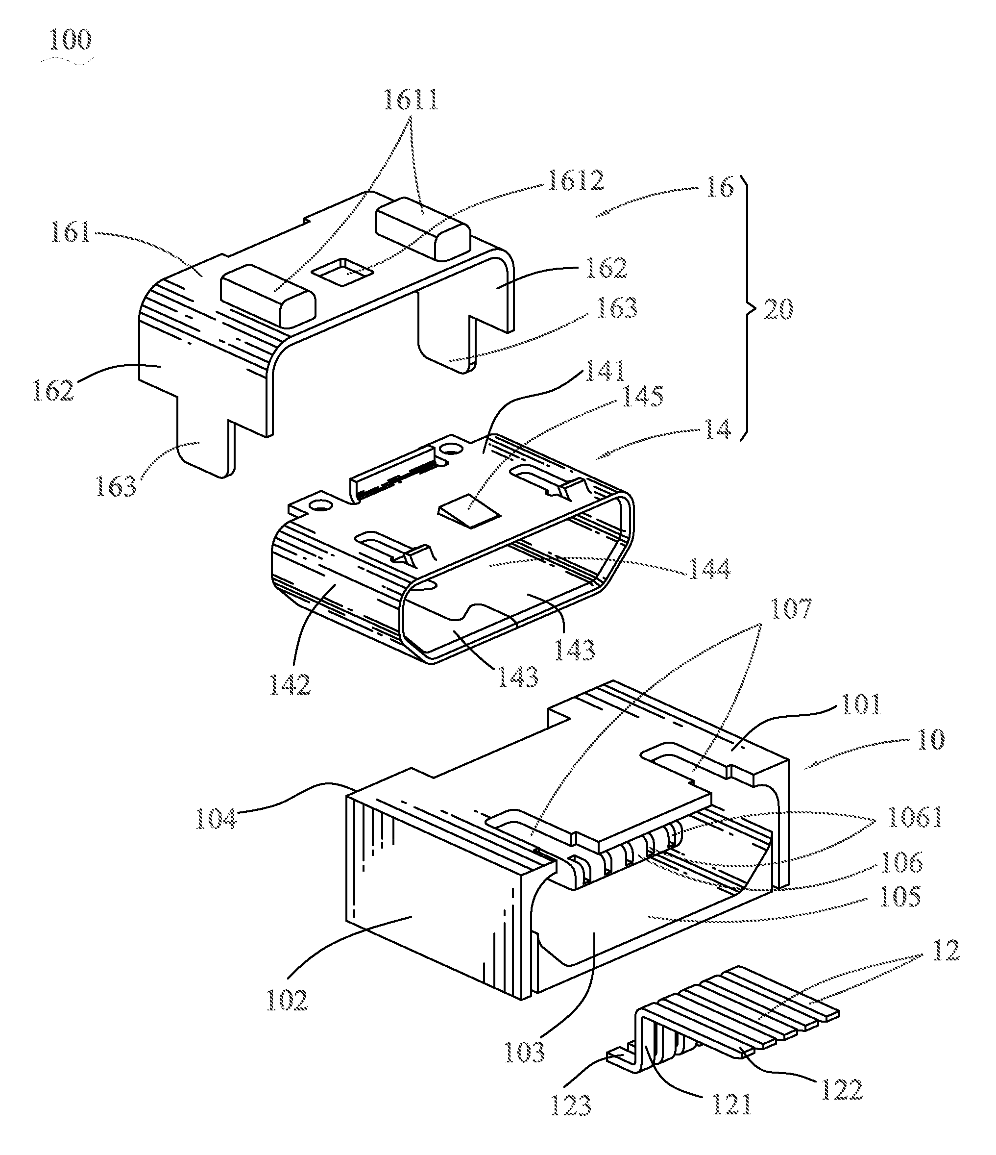
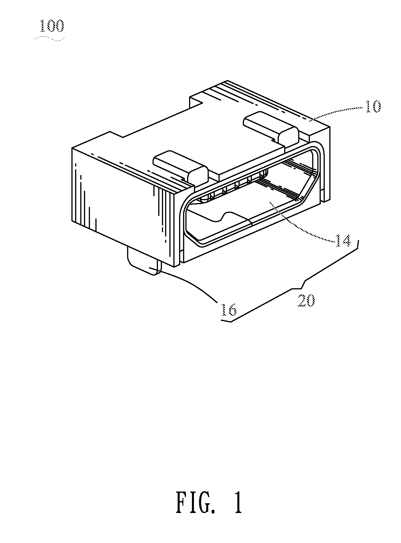
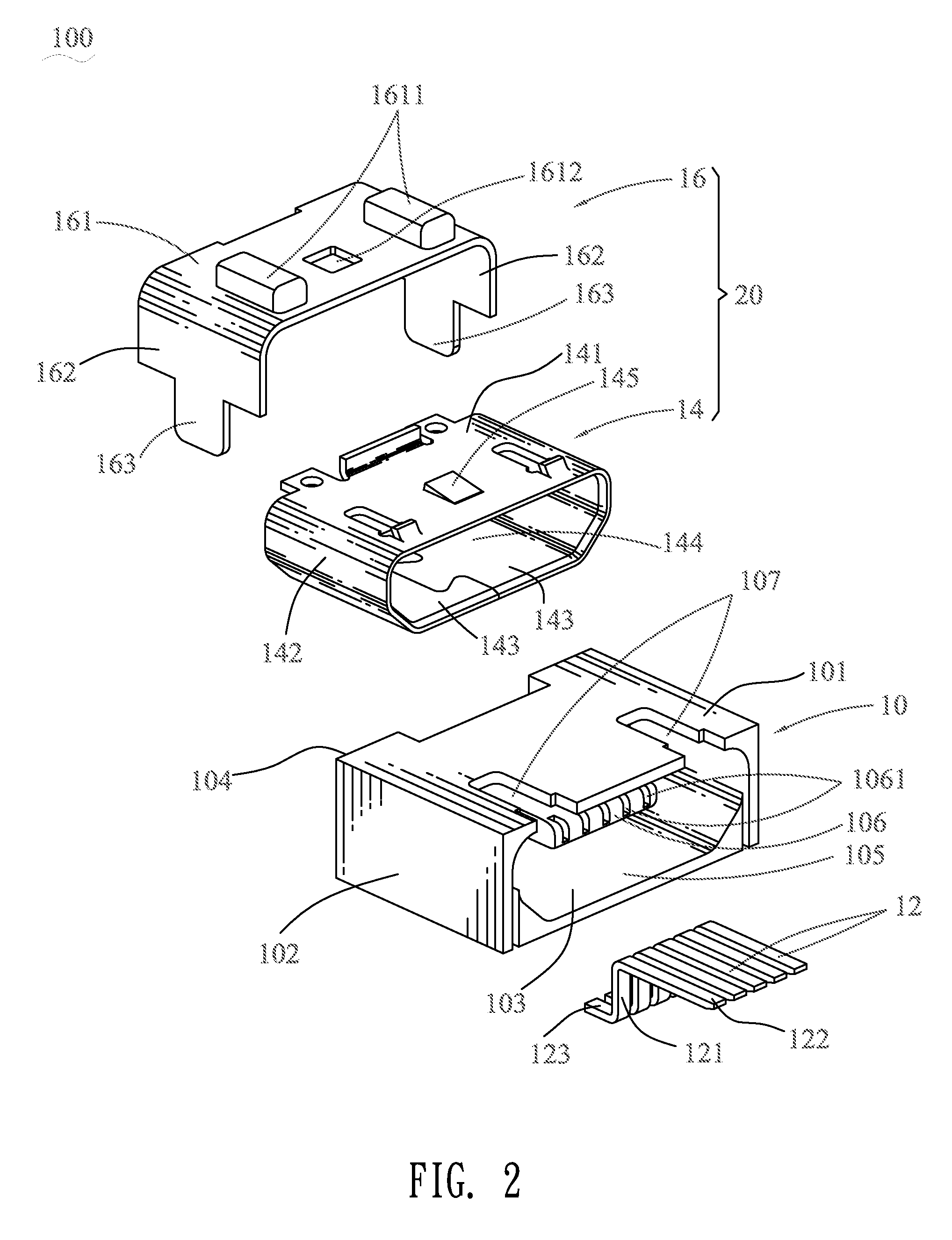
[0013]Referring to FIGS. 1-2, an electrical connector 100 according to the present invention includes an insulating housing 10, a plurality of terminals 12 molded in the insulating housing 10, and a shielding shell 20.

[0014]Referring to FIGS. 1-3, the insulating housing 10 is molded in a mold by injecting fluent molten plastics into the mold (not shown). The insulating housing 10 has a top wall 101, two side walls 102, a bottom wall 103 and a rear wall 104 which are interconnected to form a box shape with an accommodating chamber 105 formed thereamong. A middle of a front of the rear wall 104 protrudes forward to form an inserting portion 106 stretching into the accommodating chamber 105. The inserting portion 106 defines a plurality of terminal grooves 1061 passing through a front thereof. Two portions of the top wall 101 are cut off to define two assembling grooves 107 vertically penetrating therethrough and passing through a front of the top wall 101. Each of the two side walls 1...


PUM


Abstract

An electrical connector includes an insulating housing, a plurality of terminals and a shielding shell which are molded integrally. The insulating housing has a top wall, two side walls, a bottom wall and a rear wall which are interconnected to form a box shape with an accommodating chamber formed thereamong. The terminals are molded in the insulating housing with contact portions extended into the accommodating chamber. The shielding shell includes an inner shell and an outer shell fixedly attached on the inner shell. The inner shell includes a top plate, two side plates and a bottom plate which are interconnected together to surround a receiving space thereamong. The shielding shell is molded in a periphery of the accommodating chamber with a portion of the outer shell exposed outside the insulating housing.

Description

BACKGROUND OF THE INVENTION[0001]1. Field of the Invention[0002]The present invention generally relates to an electrical connector, and more particularly to an electrical connector having an insulating housing and a shielding shell capable of being combined with each other completely tightly and simply and a molding method thereof.[0003]2. The Related Art[0004]Currently, a common connector includes an insulating housing, a plurality of terminals molded in the insulating housing, a shielding shell enclosing the insulating housing. When the connector is assembled, the terminals are firstly molded in the insulating housing, and then the insulating housing is inserted into the shielding shell. The insulating housing and the shielding shell are generally assembled together by means of a buckling method, so the insulating housing and the shielding shell can't be assembled completely tightly, and a gap is formed thereamong.[0005]When the above-mentioned connector is used, it's often expose...

Claims


Application Information

Patent Timeline
Patent Type & Authority Patents(United States)
IPC IPC(8): H01R13/648
CPCH01R13/6581H01R43/24
Inventor CHIANG, SHU-MAN
Owner CHENG UEI PRECISION IND CO LTD
Why Eureka
Try Eureka