Frame synchronization and structure detection method in DVB-S2 system

a satellite broadcasting and frame synchronization technology, applied in the field of satellite broadcasting system frame synchronization and frame structure detection, can solve the problems of high complexity, high cost, and limited application of conventional frame detection methods to environments with frequency errors, and achieve low cost, reduced memory space, and small memory capacity

Inactive Publication Date: 2011-12-27
ELECTRONICS & TELECOMM RES INST +1
View PDF20 Cites 7 Cited by
  • Summary
  • Abstract
  • Description
  • Claims
  • Application Information

AI Technical Summary

Benefits of technology

[0019]The frame sync and structure detecting method of the present invention can calculate differential correlation values of reception symbols, generate index sequences of the symbols exceeding a threshold value, and detects a frame sync and frame structure at positions estimated as frame start points corresponding to a total number of frames according to the number of positions where the above-generated index sequences are matched by using the number of symbols per frame for each frame structure in a satellite broadcasting system. The frame sync and structure detecting method can detect frame sync and frame structure with low complexity and small memory capacity.
[0020]Also, the method of the present invention can reduce memory space in a receiver for a satellite broadcasting system employing adaptive modulation and coding schemes.
[0021]In addition, the method of the preset invention can improve performance of a receiver by overcoming mis-detection and false-alarm that may occur in the course of hard decision for storing data in a memory.

Problems solved by technology

However, the conventional frame detection method requires an additional process for correcting frequency and phase errors in the PLSC decoding.
Therefore, there is a limit in applying the conventional frame detection method to an environment with frequency errors.
Particularly, the conventional frame detection method using a maximum value has a problem in that it requires a high-volume memory space and high complexity.
Therefore, the technology cannot be applied to frames with fixed sync words, such as frames of a DVB-S2 system.

Method used


Image

  • Frame synchronization and structure detection method in DVB-S2 system
  • Frame synchronization and structure detection method in DVB-S2 system
  • Frame synchronization and structure detection method in DVB-S2 system

Examples


Embodiment Construction

[0030]The advantages, features and aspects of the invention will become apparent from the following description of the embodiments with reference to the accompanying drawings, which is set forth hereinafter. When it is considered detailed description on a related art may obscure the point of the present invention, the description will not be provided. Hereinafter, specific embodiments of the present invention will be described in detail with reference to the accompanying drawings.

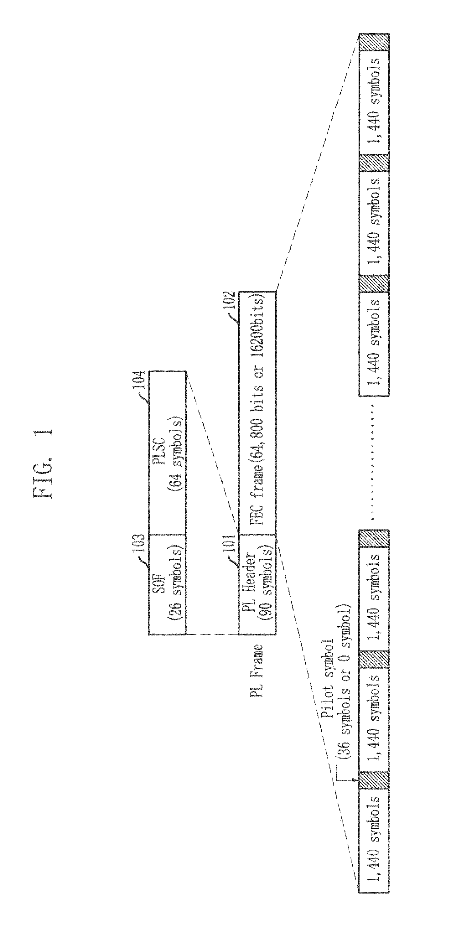
[0031]FIG. 1 illustrates a transmission frame of a Digital Video Broadcasting-Satellite 2 (DVB-S2) system in accordance with an embodiment of the present invention.

[0032]Referring to FIG. 1, the transmission frame of the DVB-S2 system, to which the present invention is applied, includes a Start of Frame (SOF) 103 having 26 symbols, a physical layer (PL) header 101 including a physical layer signaling code (PLSC) 104 having 62 symbols, and a forward error correction (FEC) frame 102 having a pilot symbol and ...


PUM


Abstract

Provided is a method for detecting frame sync and frame structure in a satellite broadcasting system. The method for detecting frame sync and frame structure includes the steps of: calculating differential correlation values of reception symbols; generating index sequences of reception symbols whose differential correlation values calculated above exceed a threshold value; calculating positions estimated as frame start points which correspond to a total frame number based on the number of symbols per frame for each frame structure; and detecting frame sync and frame structure based on the umber of positions where the above-calculated frame start point estimated positions and the above-generated index sequences are matched.

Description

TECHNICAL FIELD[0001]The present invention relates to a method for detecting frame sync and frame structure in a satellite broadcasting system; and, more particularly, to a frame sync and structure detecting method that can calculate differential correlation values of reception symbols, generate index sequences of the symbols exceeding a threshold value, and detects a frame sync and frame structure at positions estimated as frame start points corresponding to a total number of frames according to the number of positions where the above-generated index sequences are matched by using the number of symbols per frame for each frame structure in a satellite broadcasting system.[0002]This work was supported by the IT R&D program of MIC / IITA [2005-S-013-02, “Development of Broadband Adaptive Satellite Communications and Broadcasting Convergence Technology”].BACKGROUND ART[0003]Specific embodiments of the present invention will be described by taking a Digital Video Broadcasting-Satellite 2...

Claims


Application Information

Patent Timeline
Patent Type & Authority Patents(United States)
IPC IPC(8): H04J3/06
CPCH04L7/042H04L27/2656H04N7/20H04N21/238H04N21/2383H04N21/242H04N21/4382H04N21/6143H04H40/90H04N5/04
Inventor KIM, PAN-SOOCHANG, DAE-IGOH, DEOCK-GILKIM, SANGTAEKANG, SEOKHEONSUNG, WONJIN
Owner ELECTRONICS & TELECOMM RES INST
Why Eureka
Try Eureka