Secondary blade portion containment device

a technology for containment devices and blades, which is applied in the direction of safety/regulatory devices, sustainable transportation, climate sustainability, etc., can solve the problems of loss of control of aircraft or structural damage, severe damage to aircraft, and passengers' injuries, so as to improve the confinement of blades and improve the effect of preventing damage, variable attachment strengths, and variable failure levels

Active Publication Date: 2012-01-03
GKN AEROSPACE SERVICES STRUCTURES CORP
View PDF3 Cites 3 Cited by
  • Summary
  • Abstract
  • Description
  • Claims
  • Application Information

AI Technical Summary

Benefits of technology

[0009]According to an exemplary aspect of the current invention, a blade containment encompasses the engine casing and the blade failure path. The blade containment net may encompass areas around the engine casing in directions in which the blade portion could escape when the blade out occurs. In order to reduce space occupancy, the blade containment net may be collapsed on the surface of the engine casing during normal operation of the engine, and may only be deployed in the event of a blade out. According to various aspects of the current invention, the blade containment net may be embedded in the engine casing. Structurally, the net may be made out of any material that provides high tensile strength and low brittleness, such as a metal (e.g., a steel or other metal woven wire), as well as a composite, carbon fiber, Kevlar, or a ceramic. Other materials that provide high tensile strength and low brittleness may also compose all or portions of the net.
[0011]The energy imparted to the net and to the links of the net from the impact with the broken blade may thereby be converted from kinetic energy to dissipated energy in the net, and thus dissipated and dispersed throughout the net. According to various aspects of the current invention, the kinetic energy of the broken blade portion may be dissipated in the form of successive breaks of some or all of the links as a consequence of the impact between the net and the broken blade portion. Consequently, the blade may remain contained inside the net, and blade containment thereby improved. It should be noted that although tying is used as an example to describe the attachment of the various portions or links of the blade containment device, any other suitable technique of attachment of the links can be used, such as welding, taping, adhering, tying, bolting, and the like.
[0012]According to another aspect of the current invention, the links and various portions of the net that are attached to each other via attachment features, such as tying, may have variable attachment strengths and thus variable failure levels. Different portions of the net, or different links forming the net, may be attached to each other at different strength levels. Accordingly, some links may detach or break off upon impact with the broken blade portion at a first kinetic energy, which is the kinetic energy of the broken blade portion transferred to the net upon impact and converted into energy to produce a break of some of the links, while other links may break off upon impact at a second different kinetic energy. When a broken blade portion contacts the net and transfers its kinetic energy to the net and to the links of the net, the links may not break off from each other at the same time, but may break off variably because different links of the net may be attached to each other at different strength levels. For example, the more weakly attached links may break off first, then links that are attached with a greater strength may break off next, and links with the greatest attachment strength may break off last. As such, links break off successively on the basis of their attachment strength upon contact with the broken blade portion. As a result of this variable attachment and breaking off of the links, the kinetic energy of the broken blade portion is dissipated more efficiently, and the blade is contained more effectively.
[0013]Among other advantages of the current invention, the various aspects of the blade containment device described above provide the ability to use a light weight medium, lighter than conventional engine casings, to contain the failed blade portions because of the ability of the net to dissipate the kinetic energy transferred from the broken blade. Another advantage lies in space saving as the net can be collapsed about the engine casing and occupy minimal size during normal operation.

Problems solved by technology

During a blade out, severe damage can occur to an aircraft, such as loss of control of the aircraft or structural damage.
A broken blade portion can cause injury to the passengers of an aircraft if it penetrates the fuselage, and can also cause engine failure.

Method used


Image

  • Secondary blade portion containment device
  • Secondary blade portion containment device
  • Secondary blade portion containment device

Examples


Embodiment Construction

[0019]These and other features and advantages of this invention are described in, or are apparent from the following detailed description and figures for various exemplary aspects of a blade containment device according to the current invention.

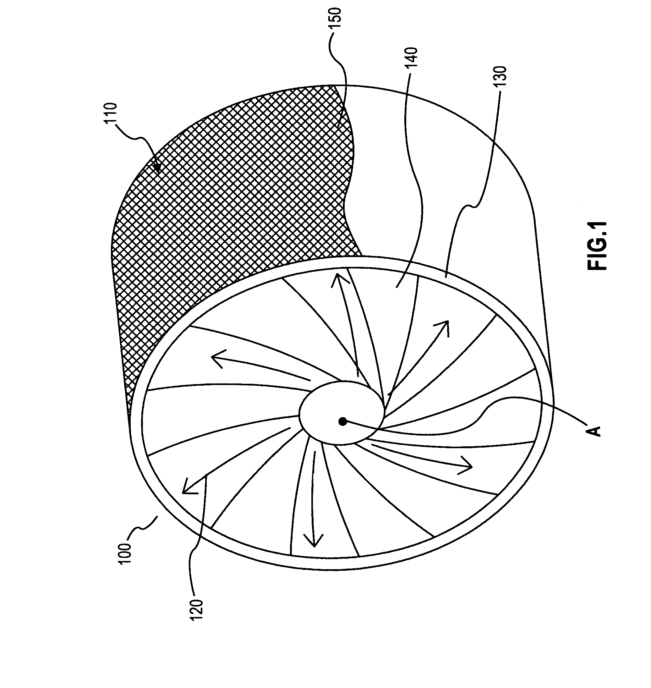
[0020]FIG. 1 is a perspective representative view of a blade containment device 100 that may encompass the nacelle or engine casing 130 of an airplane, according to an exemplary aspect of the current invention. In FIG. 1, the engine casing 130 is covered at least partially by the blade containment device which may be a flexible interwoven structure or net 150. According to various aspects of the current invention, the blade containment net 150 may be embedded in the engine casing 130. The blade containment device or net 150 may comprise a net with a mesh pattern 110. The mesh pattern may vary and may be, for example, a circumferential mesh pattern, or an axial mesh pattern. In the event of a blade failure or blade out, the net 150 may deploy ...


PUM


Abstract

A device that deploys during a blade portion failure that encompasses the engine casing is provided to prevent damage caused by the failure. A blade containment device such as a flexible interwoven structure or a net encompasses the engine casing and the blade failure path, or is embedded in the engine casing, and deploys in the event of a blade failure, such as the breaking of an engine blade. The net deploys when the blade portion has failed and has started expanding along the blade failure path, and may include a number of links attached to one another. Upon impact with a broken blade portion, thus transferring the kinetic energy of the blade portion to the net, some or all of the links may break off from each other, thus allowing the net to deploy and dissipating the kinetic energy generated by the expanding broken blade. Consequently, the blade remains contained inside the net, and blade containment is improved.

Description

[0001]This application claims priority from provisional application No. 60 / 960,573, filed on Oct. 4, 2007 in the U.S. Patent Office and titled “Secondary Blade Portion Containment Device,” and which is incorporated by reference herein in its entirety.BACKGROUND OF THE INVENTION[0002]1. Field of the Invention[0003]Aspects of the present invention relates to an engine or fan blade portion containment device, and in particular to a device that deploys during an engine or fan blade failure by capturing the failed blade in a secondary retention system on the outer structure of the engine or fan casing.[0004]2. Background of the Related Art[0005]There is a general need in the art for blade containment useful, for example, in an engine or fan blade failure condition in, for example, a jet engine or a propeller. During an engine or fan blade failure, also referred to as blade out, the blade can acquire a very high kinetic energy because of its high speed rotation inside the engine casing, a...

Claims


Application Information

Patent Timeline
Patent Type & Authority Patents(United States)
IPC IPC(8): F01B25/16
CPCF01D21/045Y02T50/672Y02T50/60
Inventor CACACE, ANTHONY
Owner GKN AEROSPACE SERVICES STRUCTURES CORP
Why Eureka
Try Eureka