Active clearance control for a centrifugal compressor

a centrifugal compressor and clearance control technology, which is applied in the direction of machines/engines, stators, liquid fuel engines, etc., can solve the problems of requiring a significant amount of power to operate, complicated linkages, and contributing significant weigh

Active Publication Date: 2012-01-03
GENERAL ELECTRIC CO
View PDF10 Cites 35 Cited by
  • Summary
  • Abstract
  • Description
  • Claims
  • Application Information

AI Technical Summary

Benefits of technology

[0006]An exemplary embodiment of the assembly includes valving controlled by an electronic controller for pressurizing and depressurizing the cavity. The valving is operably connected to a source of compressor discharge pressure air for pressurizing the cavity and may include a control pressure valve for pressurizing the cavity and depressurizing the cavity. The control pressure valve may be connected to the source of compressor discharge pressure air and to a vent line. An electronic controller may be controllably connected to the control pressure valve. The electronic controller may be operable for pulsing a solenoid of the control pressure valve many times a second for rapidly cycling the valves between open and closed states using pulse width modulation.
[0010]An alternative embodiment of the active control system assembly includes a control pressure valve for pressurizing the cavity and a blow off pressure valve for depressurizing the cavity. The control and blow off pressure valves may be inline and connected to a pressure line extending between the cavity and the source of compressor discharge pressure air. An electronic controller may be controllably connected to the control and blow off pressure valves. The electronic controller may be operable for pulsing solenoids of the control and blow off pressure valves many times a second for rapidly cycling the valves between open and closed states using pulse width modulation.
[0012]The method may further include pulsing a solenoid in the control pressure valve for opening and closing the control pressure valve many times a second for rapidly cycling the valve between open and closed states for the controlling of the cavity pressure using pulse width modulation for the pulsing of the solenoid. The method may further include measuring the cavity pressure using one or more pressure sensors positioned for measuring the cavity pressure and in signal supply communication with the electronic controller, measuring the blade tip clearance using one or more clearance sensors positioned for measuring the blade tip clearance and in signal supply communication with the electronic controller, and using output from the pressure and clearance sensors to the electronic controller for further controlling the control pressure valve for the controlling of the cavity pressure.

Problems solved by technology

These systems often include complicated linkages, contribute significant weight, and / or require a significant amount of power to operate.

Method used


Image

  • Active clearance control for a centrifugal compressor
  • Active clearance control for a centrifugal compressor
  • Active clearance control for a centrifugal compressor

Examples


Embodiment Construction

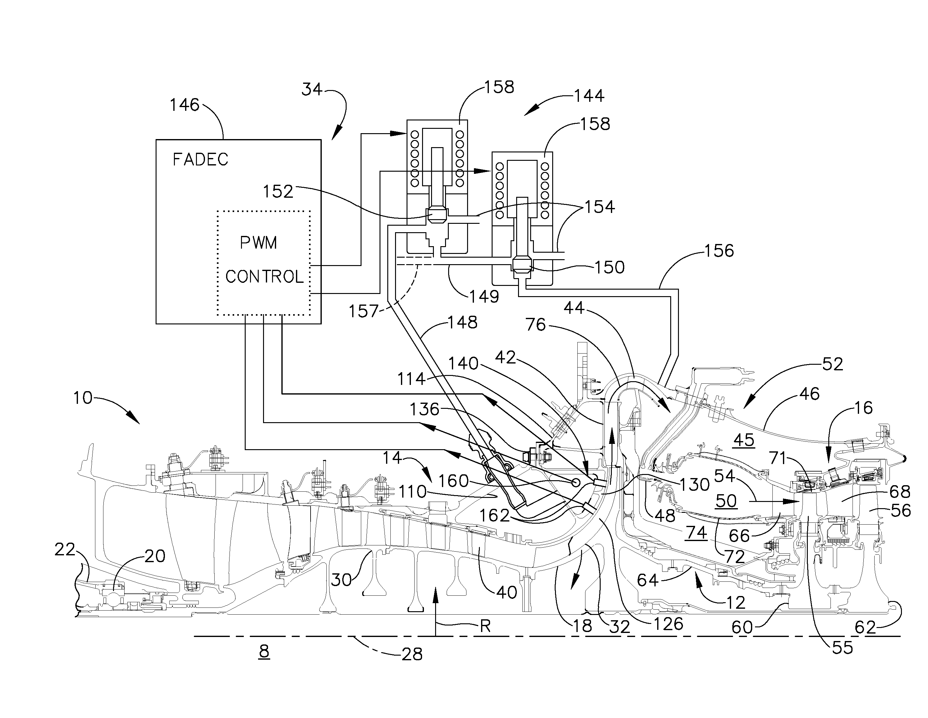
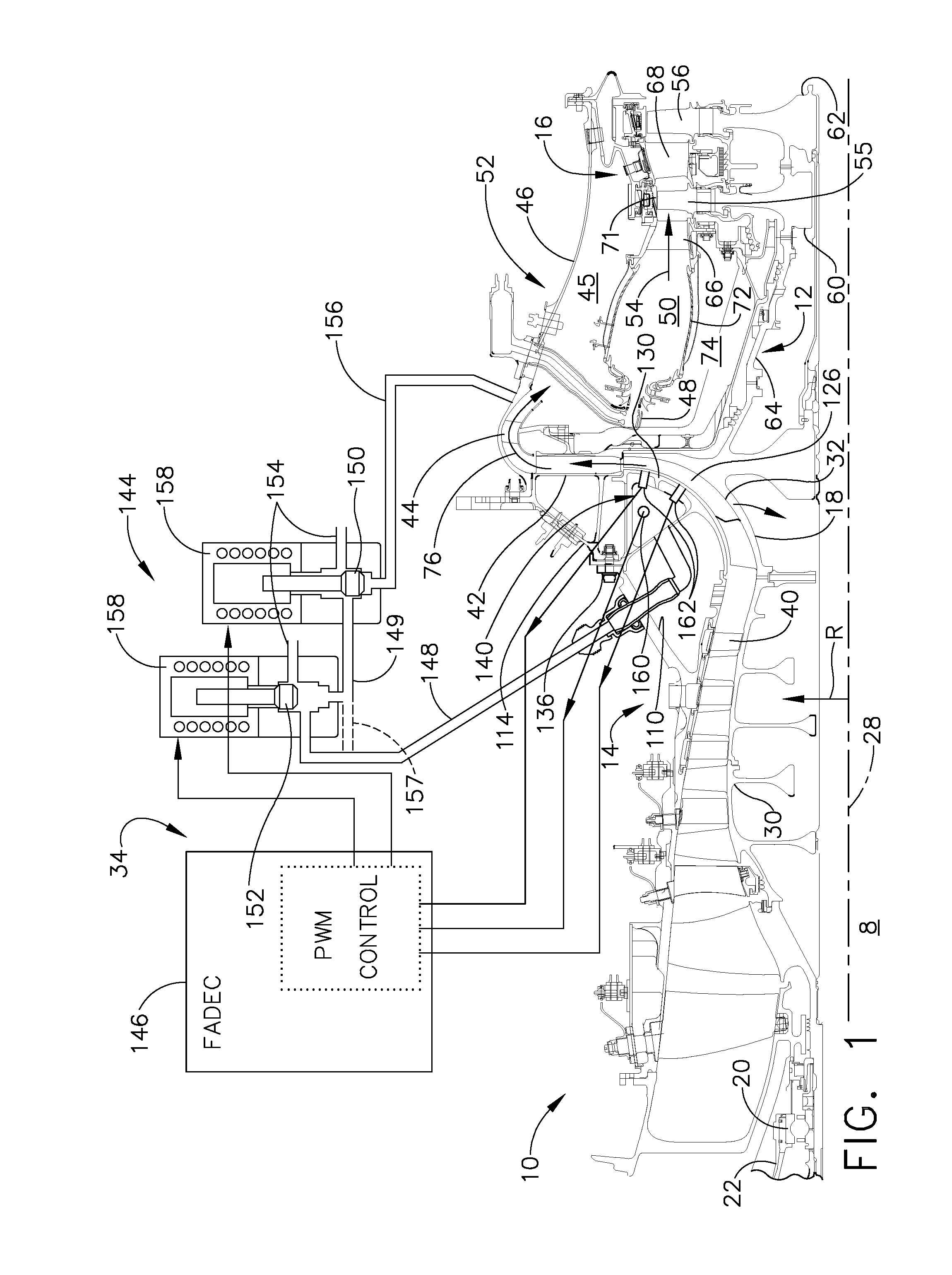
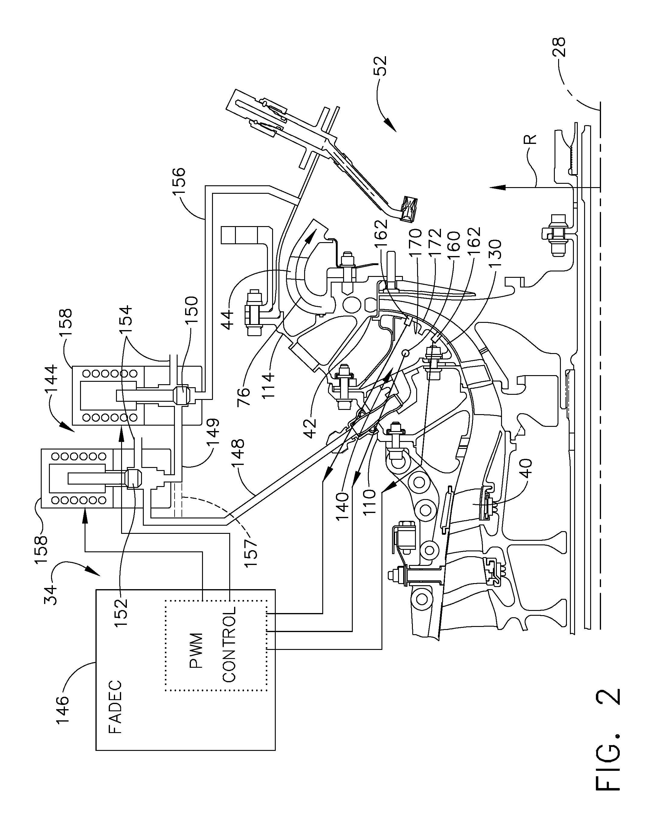
[0021]Illustrated in FIG. 1 gas turbine engine 8 with a high pressure gas generator 10 having a single stage centrifugal compressor 18 as a final compressor stage and an active control system 34 for controlling clearances or gaps in the centrifugal compressor 18. The high pressure gas generator 10 has a high pressure rotor 12 including, in downstream flow relationship of a high pressure compressor 14, a combustor 52, and a high pressure turbine 16. The rotor 12 is rotatably supported about an engine centerline 28 by a forward bearing 20 in a front frame 22 and a rear bearing (not shown) disposed downstream of turbine 16 in a turbine frame (not shown).

[0022]In the exemplary embodiment illustrated herein, the compressor 14 is a five stage axial compressor 30 followed by the single stage centrifugal compressor 18 having an annular centrifugal compressor impeller 32. Outlet guide vanes 40 are disposed between the five stage axial compressor 30 and the single stage centrifugal compressor...


PUM


Abstract

Apparatus and method of operating a centrifugal compressor and active control system includes a centrifugal compressor with compressor blades mounted on an impeller, an annular cavity bounded in part by a shroud adjacent to the blades, and an active control system for controlling a clearance between the shroud and the blades by controlling a cavity pressure in the cavity. An electronic controller for controlling a control pressure valve for pressurizing using a source of compressor discharge pressure air and depressurizing the cavity respectively may open and close the valves using pulse width modulation. Pressure and clearance sensors positioned for measuring the cavity pressure the blade tip clearance respectively in signal supply communication with the electronic controller may be used. The shroud may be supported by radially spaced apart annular radially outer and inner supports connected to a casing by a bolted joint bounding the cavity.

Description

GOVERNMENT INTERESTS[0001]The government may have rights in this invention pursuant to government contract W911W6-07-2-0002 awarded by the Department of Defense.TECHNICAL FIELD[0002]The present invention relates generally to gas turbine engines having centrifugal compressors and, more specifically, to control of clearances between an impeller and a shroud of a centrifugal compressor.BACKGROUND INFORMATION[0003]Conventional gas turbine engines having centrifugal compressors typically have an axial cold clearance between the impeller and the impeller shroud set such that a rub between them will not occur at the operating conditions that will cause the highest clearance closure which is typically a cold burst. Active clearance control systems have been developed to control radial turbine clearances between tips of axial flow radially extending turbine and compressor blades and shrouds surrounding the blades. Typically, these active clearance control systems are thermally activated and ...

Claims


Application Information

Patent Timeline
Patent Type & Authority Patents(United States)
IPC IPC(8): F01B25/26F01D25/00F03B11/02F04D29/00F03D11/00F03B11/00F01D25/24
CPCF01D11/22F04D27/0246F04D29/4206F05D2270/301F04D29/162F04D29/622
Inventor KARAFILLIS, APOSTOLOS PAVLOSLOEHLE, KENNETH ALLENTAMEO, ROBERT PATRICKGUTZ, DAVID ALLEN
Owner GENERAL ELECTRIC CO
Why Eureka
Try Eureka