Method and device for cementing a well or a pipe

Inactive Publication Date: 2012-01-10
SALTEL IND
View PDF10 Cites 8 Cited by
  • Summary
  • Abstract
  • Description
  • Claims
  • Application Information

AI Technical Summary

Benefits of technology

[0026]The device for cementing a well or a pipe, for example a casing, having a portion to be treated, in particular to be repaired and/or plugged, which device also forms the subject matter of the invention, is characterised in that it comprises an assembly which is designed to be introduced into the well or pipe and to be positioned opposite the portion to be cemented, this assembly consisting of a tubular mandrel and an inflatable membrane which is also tubular and surrounds said mandrel, the wall of the membrane being made of a flexible and elastic material which can expand radially under the effect of an internal pressure, means being provided for introducing a pressurised fluid into said membrane in o

Problems solved by technology

Over time, a portion of the wall of the casing may have to be sealed, in particular if has deteriorated, for example due to premature wear and / or cracking, or when the perforations intended for the passage of oil have to be plugged, in particular because the deposit has been depleted in this zone and undesirable fluid products (in particular water or gas) risk passing through the wall of the casing and penetrating into the latter.
The first technique is time-consuming and expensive and may cause exploitation problems, in particular due to the fact that it is necessary to completely neutralise the well prior to any intervention.
The second technique is complicated, expensive and can be used only in a certain limited number of configurations, due to the fact that the completion equipment generally has a much smaller diameter than that of the lower zone of the casing in which the portion to be treated is located.
In particular, the installation of a cement coating is generally not possible using this technique.

Method used


Image

  • Method and device for cementing a well or a pipe
  • Method and device for cementing a well or a pipe
  • Method and device for cementing a well or a pipe

Examples


Embodiment Construction

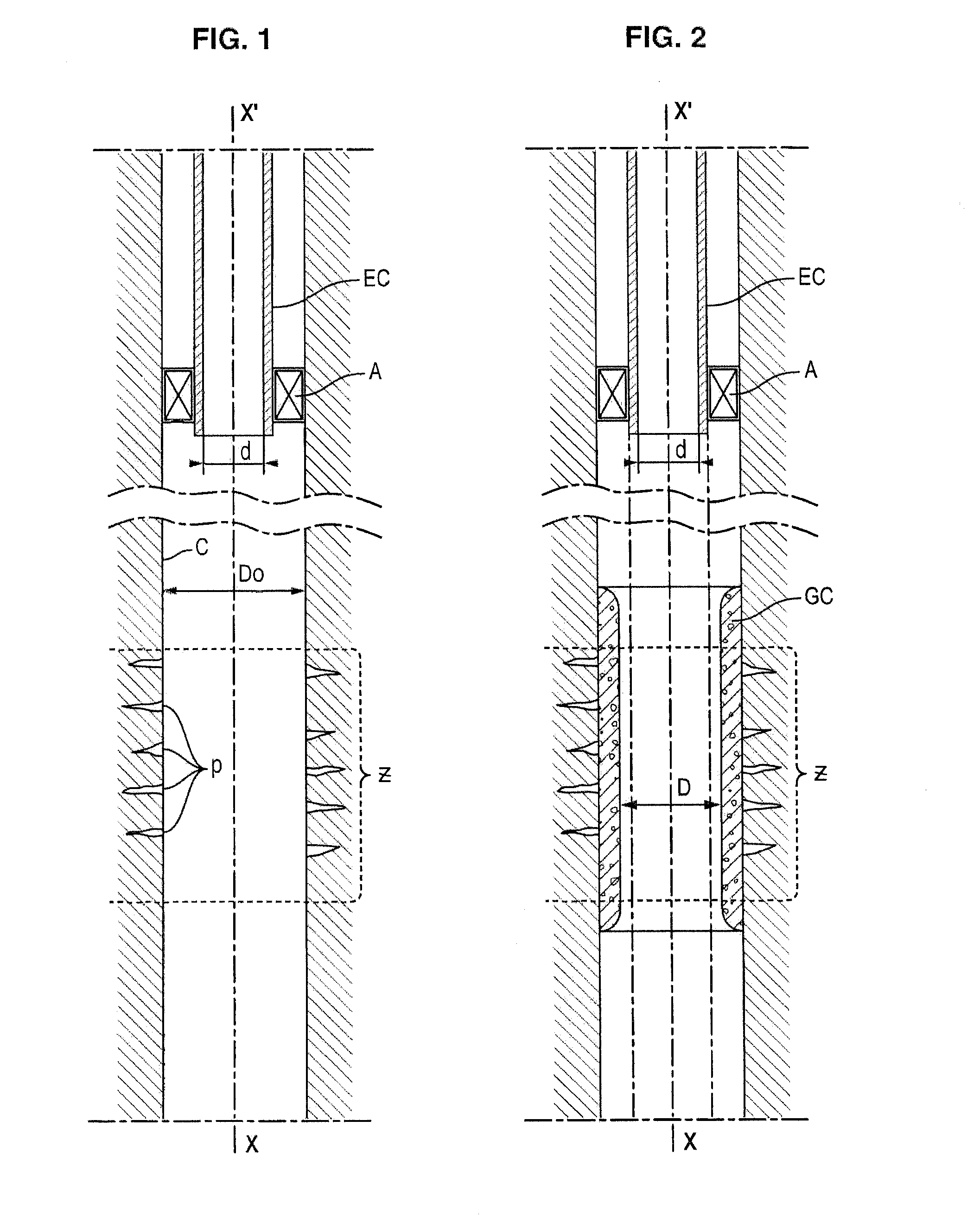
[0052]FIG. 1 shows part of an oil drilling well, lined with a casing C with a cylindrical wall and of vertical axis X-X′. A portion Z of this casing has for example perforations p, producing water, which it is desired to plug by means of cementing.

[0053]Reference EC denotes completion equipment, held in place by an annular centring element A, and the internal diameter d of which is much smaller than the diameter D0 of the casing.

[0054]By way of example, the diameter d is around 69 mm whereas the diameter D0 is around 155 mm.

[0055]FIG. 2 shows the same well part after installing a cement coating GC in the portion Z.

[0056]In order not to disrupt exploitation of the well, it is important that the internal diameter D of this coating is greater than d.

[0057]It will be understood that this installation usually poses difficulties when it takes place through the completion equipment EC.

[0058]As will now be explained, the invention nevertheless makes it possible to carry out this procedure e...


PUM


Abstract

Introducing within a well or pipe a mandrel equipped with an inflatable membrane which can expand radially under the effect of an internal pressure. Positioning the mandrel opposite the portion to be treated, in introducing a pressurized fluid within the membrane such that its end regions form annular bulges pressing firmly against the wall, whereas its mid-region expands to a lesser degree. Forming a peripheral annular space into which is then injected a cement which is liquid but able to harden. Leaving the cement to set so as to form a solid sleeve. Deflating the tubular membrane. Withdrawing the mandrel together with the deflated membrane. The method can be used in the oil sector, particularly for repairing and / or plugging a portion of casing.

Description

BACKGROUND OF INVENTION[0001]The present invention relates to a method and a device for cementing a well or a pipe, for example a casing, having a portion to be treated so as to make it leaktight, in particular to be repaired and / or plugged.[0002]It applies more particularly, but not necessarily, to the field of oil production.[0003]The casing is a metal tube which lines the interior of the oil well over a considerable length.[0004]As an indication, this length is for example between 2000 and 4500 meters, whereas its internal diameter is between 120 and 200 millimeters.[0005]In the lower part, the casing is perforated at the level of the deposit(s) that it passes through, so as to allow the passage of oil or a gaseous hydrocarbon.[0006]Located in the upper part of the well is the wellhead, which is equipped with various systems, in particular for protection, suspension and sealing purposes.[0007]Over a considerable length of the upper part of the well, for example between 1500 and 4...

Claims


Application Information

Patent Timeline
IPC IPC(8): E21B33/00
CPCE21B29/10E21B33/127F16L55/16455
Inventor SALTEL, JEAN-LOUIS
Owner SALTEL IND
Why Eureka
Try Eureka