
LED lamp tube with heat distributed uniformly

a technology of led lamp tube and heat distribution, which is applied in the field of lamp tube, can solve the problems of reducing the lifetime of led lamp tube, premature damage to the proportion of led lamp, and waste of unburned led lamps, so as to facilitate heat dissipation and reduce the temperature

Active Publication Date: 2012-01-10
KITAGAWA HLDG
View PDF1 Cites 40 Cited by
  • Summary
  • Abstract
  • Description
  • Claims
  • Application Information

AI Technical Summary

Benefits of technology

"The present invention is about providing an LED lamp tube with even distribution of heat. The invention achieves this by arranging the electronic elements connected to the circuit board uniformly, so that the heat generated by the electronic elements is evenly distributed throughout the LED lamp tube. This reduces the temperature and makes it easier to dissipate the heat. The LED lamp tube includes a hollow transparent tube, a LED lamp assembly, two conductive caps, and a circuit control unit. The circuit control unit is made up of multiple separated sub-portions that are evenly distributed on the LED lamp assembly's circuit board."

Problems solved by technology

Even, a portion of the LED lamp 21a may suffer damage prematurely due to poor heat-dissipating effect.
Thus, the lifetime of the LED lamp tube is reduced a lot, which also results in the waste of unburned LED lamp 21a.

Method used


Image

  • LED lamp tube with heat distributed uniformly
  • LED lamp tube with heat distributed uniformly
  • LED lamp tube with heat distributed uniformly

Examples


first embodiment

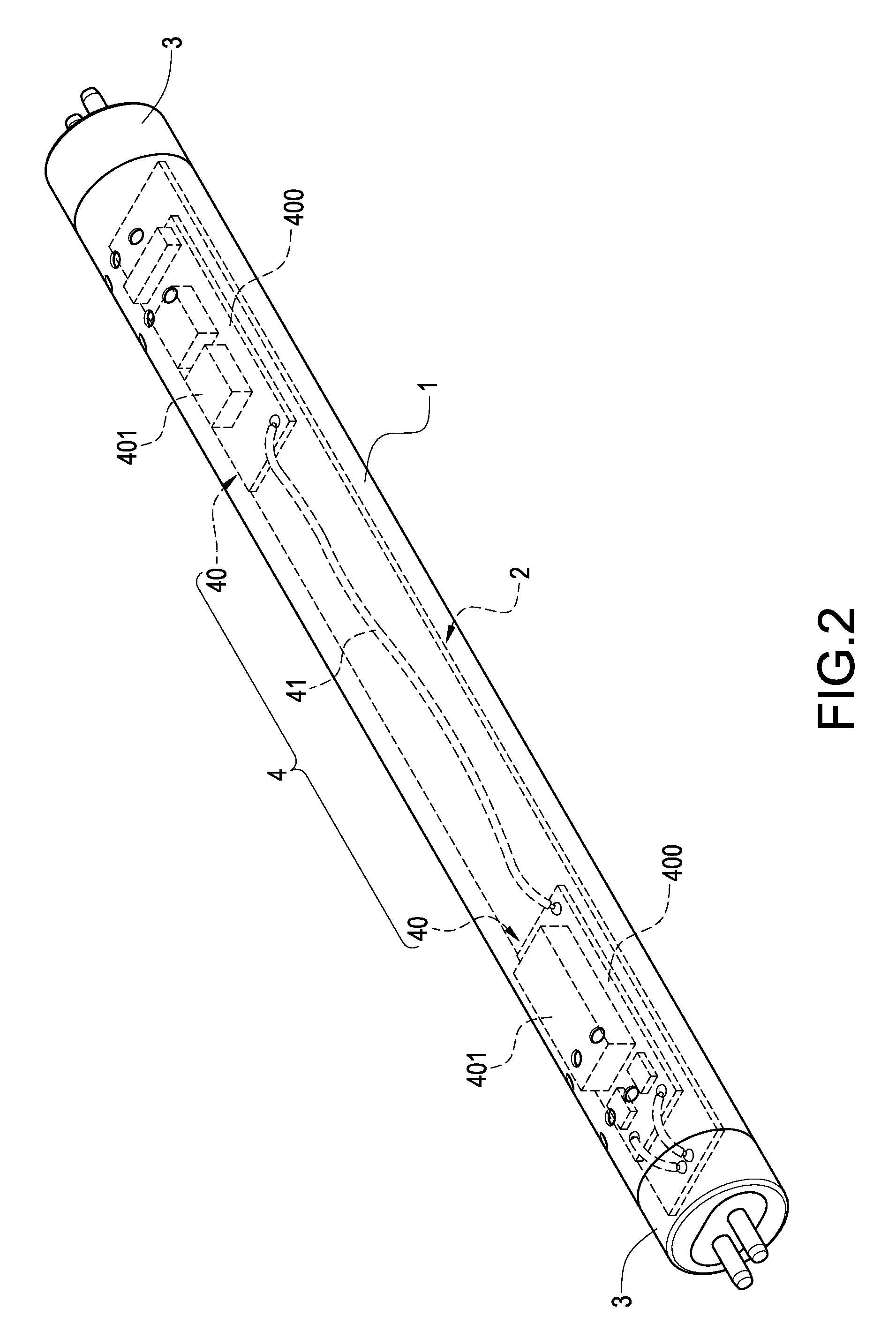
[0014]Please refer to FIGS. 2 and 3, which are a perspective view and a cross-sectional view showing the present invention respectively. The present invention is to provide a LED lamp tube with heat distributed uniformly, which includes a transparent tube 1, a LED lamp assembly 2, two conductive caps 3, and a circuit control unit 4.

[0015]The transparent tube 1 is a hollow elongate tube with two open ends. The transparent tube 1 is made of light-transmitting materials for receiving the LED lamp assembly 2 and the circuit control unit 4.

[0016]The LED lamp assembly 2 comprises a circuit board 20 horizontally arranged in the transparent tube 1, and a plurality of LED lamps 21 arranged on the downwardly-facing surface of the circuit board 20, as shown in FIG. 3. The LED lamps 21 are light-emitting diodes that are arranged on the circuit board 20 and are accommodated in the transparent tube 1 together with the circuit board 20. The LED lamps 21 illuminate a side peripheral wall surface of...

second embodiment

[0020]Furthermore, as shown in FIG. 4, in the present invention, the circuit board control unit 4 is divided into three sub-portions 40, thereby arranging the circuit control unit 4 more uniformly. Therefore, the number of the sub-portions 40 divided from the circuit control unit 4 is determined based on the number of actual heated points of the LED lamp tube, and thus the number of sub-portions is not limited to two or three.

[0021]Therefore, via the above constitution, the LED lamp tube with heat distributed uniformly can be obtained.


PUM


Abstract

A LED lamp tube which includes a hollow transparent tube, a LED lamp assembly disposed in the transparent tube, two conductive caps provided on both ends of the transparent tube respectively, and a circuit control unit. The circuit control unit includes a plurality of separated sub-portions. The respective sub-portions of the circuit control unit are distributed uniformly on the circuit board of the LED lamp assembly. Via the uniform arrangement of respective sub-portions of the circuit control unit, the heat within the LED lamp tube can be distributed uniformly, thereby lowering the temperature and facilitating the heat dissipation.

Description

BACKGROUND OF THE INVENTION[0001]1. Field of the Invention[0002]The present invention relates to a lamp tube, and in particular to a LED lamp tube for replacing a fluorescent lamp.[0003]2. Description of Prior Art[0004]As shown in FIG. 1, the conventional LED lamp tube has a glass-made tube 1a and a LED lamp assembly 2a. The LED lamp assembly 2a comprises a circuit board 20a disposed horizontally and transversely in the tube 1a. On the downwardly-facing surface of the circuit board 20a is provided with a plurality LED lamps 21a (i.e. light-emitting diodes), while the upwardly-facing surface is provided with a circuit control unit 22a for converting into currents and voltages suitable for the light-emitting diodes. Further, both ends of the tube 1a are provided with a conductive cap 10a and are electrically connected with the circuit board 20a respectively. Via the above arrangement, a LED lamp tube having a plurality of light-emitting diodes is formed, thereby replacing traditional ...

Claims


Application Information

Patent Timeline
Patent Type & Authority Patents(United States)
IPC IPC(8): F21S4/00F21V21/00
CPCF21K9/00F21K9/17H05K1/141F21V23/006H01L2924/19107F21Y2101/02H05K2201/1003H05K2201/10106H05K2201/10287F21Y2103/003Y10S362/80H05K3/222F21K9/278F21Y2103/10F21Y2115/10
Inventor LIN, KUO-LENLIN, CHEN-HSIANGLIU, WEN-JUNGWANG, HWAI-MINGHSU, KENCHENG, CHIH-HUNG
Owner KITAGAWA HLDG
Learn More