
Pneumatic card transport system

a technology of pneumatic cards and transport systems, applied in the field of pneumatic card transport systems, can solve the problems of surface information stored on cards may be corrupted or erased, and the wear and tear of cards and conveying duct surfaces can be greatly reduced, and the maintenance requirements can be greatly simplified. , the effect of improving the longevity of cards

Inactive Publication Date: 2012-01-10
YANG DAI QIANG +2
View PDF15 Cites 17 Cited by
  • Summary
  • Abstract
  • Description
  • Claims
  • Application Information

AI Technical Summary

Benefits of technology

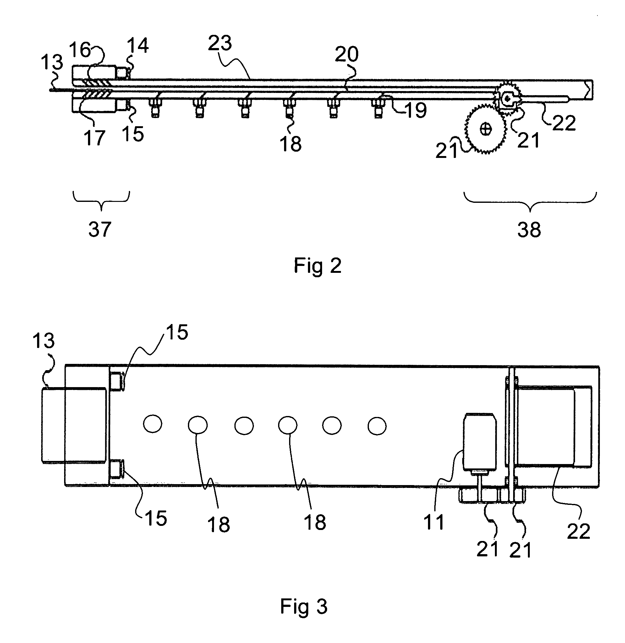
[0013]There are many advantages to the present invention. Since the card is gliding and floating along the conveying duct as it travels from the first end to the second, it makes zero or minimum contacts with the inner surface of the conveying duct. Hence the wears and tears of the card and of the conveying duct surface are greatly reduced. It is therefore most suitable for cards that are reused frequently. This will improve the longevity of the card. As the number of moving parts in the entire system is reduced to minimum, the maintenance requirements can be greatly simplified. Hence card transport systems according to the present invention are highly suitable for situations that call for low operating cost and high environmental consciousness.
[0014]Another advantage of the present invention is that the card can travel at a higher speed as friction caused by physical contacts is reduced to minimum. As a result, the speed and efficiency of the present system are improved.

Problems solved by technology

As the belt makes physical contact to the card and relies on frictional force to drag it along, surface wear and tear on the card may develop; and the information stored onto it may be corrupted or erased.

Method used


Image

  • Pneumatic card transport system
  • Pneumatic card transport system
  • Pneumatic card transport system

Examples


Embodiment Construction

[0021]The following description refers to the accompanying figures which form a part hereof and which also illustrate the embodiments of the present invention. It is understood that other embodiments can be made with structural and operational changes and they will still fall into the scope of the present invention.

[0022]As used herein and in the claims, “comprising”, “having” and “including” means including the following elements but not excluding others; and “air” is preferably atmospheric air, but may also include any gas that has aerodynamic properties capable of operating a pneumatic system.

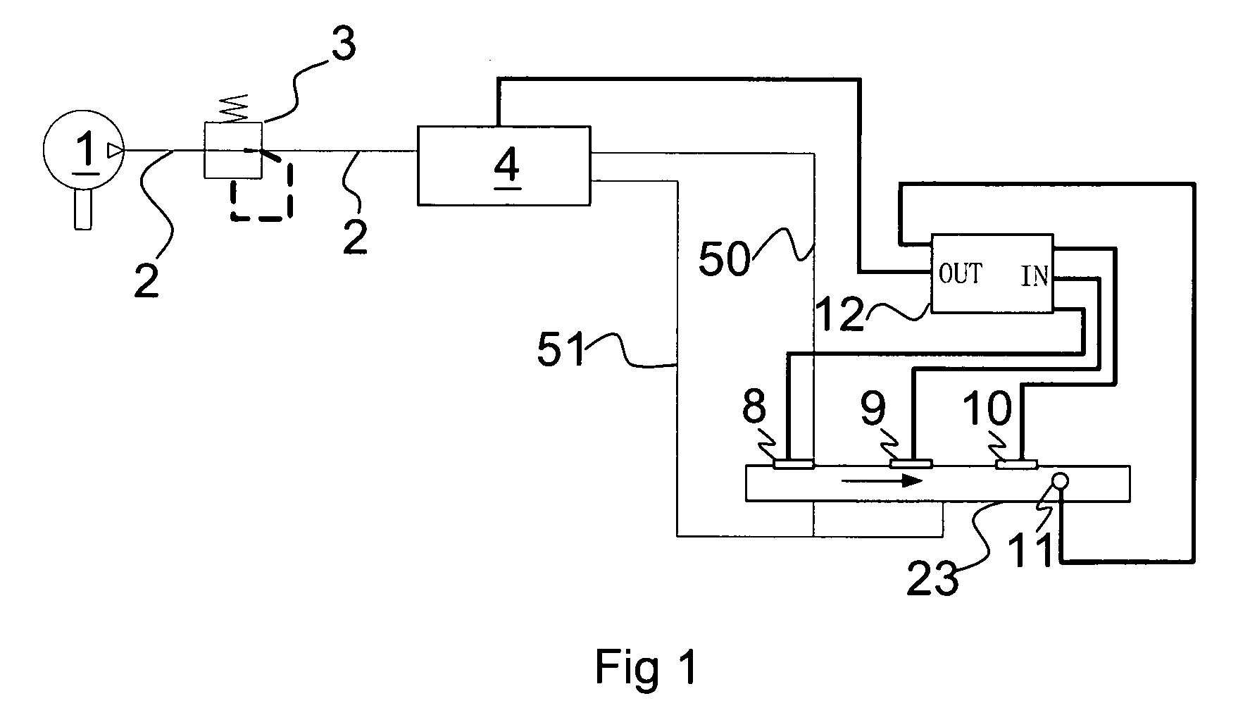
[0023]Referring now to FIG. 1 an exemplary embodiment of the card transport system in the present invention comprises a card passageway assembly 23, a pneumatic subsystem that generates and distributes pressurized air, and an electronic control unit 12 that monitors and controls the overall system. The pneumatic subsystem comprises an air compressor 1, a main pressure regulation valve 3, an ...


PUM


Abstract

A pneumatic card transport system is disclosed. The system is configured to use pressurized air to transport a card inserted to a conveying duct inside a card passageway assembly from a first end to a second end. Air nozzles are configured to release the pressurized airstreams at an angle relative to the conveying duct so that the card is essentially floating when traveling along the conveying duct. Hence, the card makes zero or minimum contact with the inner surface of the conveying duct. This will not only reduce the wear and tear of the card, but also reduces the traveling time inside the conveying duct.

Description

CROSS-REFERENCE TO RELATED APPLICATION[0001]This application is a continuation-in-part of U.S. Ser. No. 11 / 468,308, filed on Aug. 30, 2006, which claims benefit of Chinese patent application Ser. No. 200510086678.7, filed on Oct. 21, 2005, both of which are hereby incorporated by reference herein in their entirety.FIELD OF INVENTION[0002]This invention relates a card or ticket transport system. In particular, the present invention relates to systems that use pneumatic means to transport the card or the ticket.BACKGROUND OF INVENTION[0003]Cards and tickets have been widely used in many industries for purposes such as identification and recording. For the purpose of the following discussion, we refer a card to a flat, thin piece of media generally made of paper, cardboard or plastic. Hence, a card as used herein not only refers to the credit card or smart card that conforms to the ISO-7816 standard, but also cards with different sizes and shapes, including paper cards that may general...

Claims


Application Information

Patent Timeline
Patent Type & Authority Patents(United States)
IPC IPC(8): B65G35/00
CPCB65H5/228G06K13/107B65H2404/611B65H2406/112B65H2406/1132B65H2701/1914B65H2701/1936
Inventor YANG, DAI QIANGHE, FENGLI, KE WEI
Owner YANG DAI QIANG
Learn More