
Main spindle device for machine tool and machine tool

a spindle device and machine tool technology, applied in the direction of metal-working machine components, maintenance and safety accessories, metal-working apparatus, etc., can solve the problems of reducing processing efficiency, tool vibrating, and reducing processing accuracy of a processed surface of a workpiece, so as to improve processing accuracy and improve processing efficiency.

Active Publication Date: 2018-12-25
MAKINO MILLING MASCH CO LTD
View PDF13 Cites 0 Cited by
  • Summary
  • Abstract
  • Description
  • Claims
  • Application Information

AI Technical Summary

Benefits of technology

The invention relates to a spindle device of a machine tool that improves processing accuracy and prevents tool vibration during processing. The device includes a rigidity switching device that supports a bearing case with high or low rigidity based on the diameter of the tool fitted to the spindle. This prevents vibration-related processing accuracies issues, such as chattering marks or reduced processed surface quality. The spindle device reduces vibration and improves processing efficiency, resulting in better processed surfaces.

Problems solved by technology

In other words, a reaction force applied to the tool which is currently processing a workpiece may cause the tool to vibrate.
When the tool vibrates, processing accuracy of a processed surface of the workpiece is reduced, and processing efficiency is also reduced.
In particular, when processing such as cutting is carried out by using a tool having a small diameter or a tool having a long length, vibration occurs more easily.
As result, processing accuracy (processed surface quality) or processing efficiency is reduced in some cases, for example, chattering marks may be formed on the processed surface.
However, when the support rigidity of the spindle is enlarged, damping performance of the vibration of the spindle is lowered.
However, in this case, a special tool is required to be used, resulting in a normal tool that may not be used.

Method used


Image

  • Main spindle device for machine tool and machine tool
  • Main spindle device for machine tool and machine tool
  • Main spindle device for machine tool and machine tool

Examples


Embodiment Construction

[0027]Referring to FIGS. 1 to 7, a spindle device of a machine tool according to an embodiment of the present invention will be described. The spindle device which rotates a spindle having a tool fitted thereto can be disposed in any machine tool. For example, the spindle device can be disposed in a machine tool such as a horizontal or vertical machining center, a milling machine, or a boring machine.

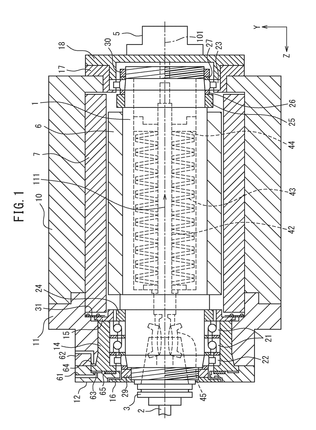
[0028]FIG. 1 is a schematic partial sectional view of the spindle device according to the embodiment. The spindle device includes a spindle 1 for supporting a tool 2, and a housing in which the spindle 1 is disposed. The housing according to the embodiment includes a spindle head housing 10, a front housing 11, and a front end housing 12.

[0029]The spindle device according to the embodiment includes a built-in type rotary machine. A stator 7 is disposed on an inner surface of the spindle head housing 10. A rotor 6 is disposed on an outer surface of the spindle 1. The stator 7 and the rot...


PUM

PropertyMeasurementUnit
diameteraaaaaaaaaa
rigidityaaaaaaaaaa
diameteraaaaaaaaaa

Abstract

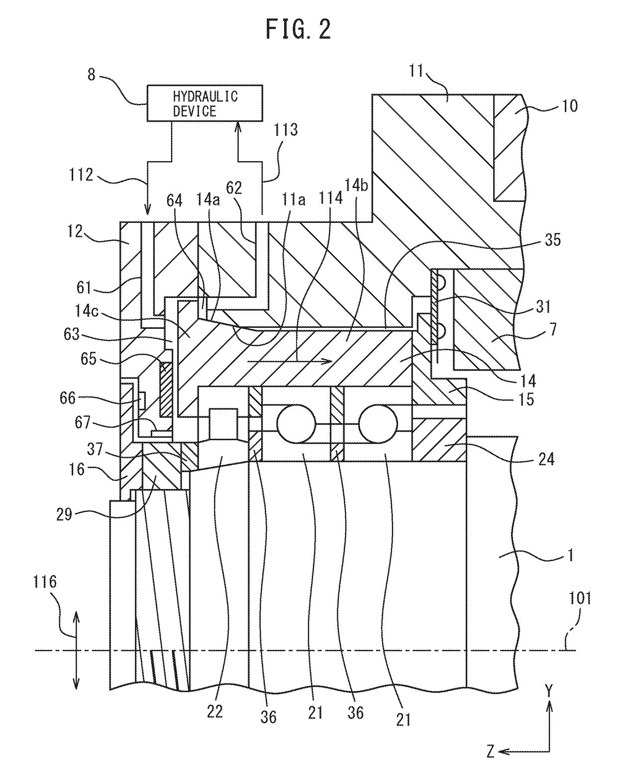
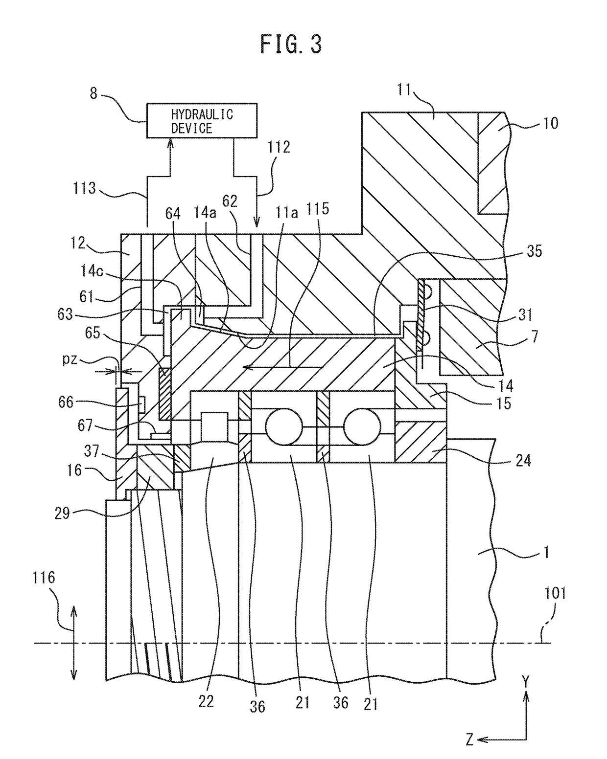
The main spindle device for a machine tool is provided with: a bearing for rotatably supporting the main spindle; a bearing case for holding the bearing; a housing inside which the bearing case is disposed; and a stiffness-switching device, which supports the bearing case with respect to the housing and is able to switch the stiffness of the bearing case support between multiple levels. When the stiffness-switching device is supporting the bearing case at a low stiffness, the main spindle device is formed so that the bearing case slides with respect to the housing. A friction member is disposed on the area where the bearing case slides with respect to the housing.

Description

CROSS-REFERENCE TO RELATED APPLICATIONS[0001]This application is a U.S. National Phase patent application of International Patent Application No. PCT / JP2013 / 067916, filed Jun. 28, 2013, which is hereby incorporated by reference in the present disclosure in its entirety.FIELD OF THE INVENTION[0002]The present invention relates to a spindle device of a machine tool, and the machine tool.BACKGROUND ART[0003]There has hitherto been known a machine tool which carries out processing such as cutting by moving a tool relative to a workpiece. The machine tool comprises a spindle device including a spindle to which the tool is fitted and a motor or the like for rotating the spindle. The spindle device is generally formed so that the tool can be replaced, and a plurality of processes can be carried out by tool replacement.[0004]Patent Literature 1 discloses a peripheral velocity switching device which can change a preload of a bearing of the spindle, and switches a bearing set of the spindle a...

Claims


Application Information

Patent Timeline
Patent Type & Authority Patents(United States)
IPC IPC(8): B23Q1/26B23Q1/70B23Q11/00
CPCB23Q1/265B23Q11/0032B23Q1/70Y10T409/304312Y10T409/309352Y10T409/309464
Inventor NEBUKA, TEPPEI
Owner MAKINO MILLING MASCH CO LTD
Learn More