Traveling band screen machine

Active Publication Date: 2012-01-10
PASSAVANT - GEIGER
View PDF35 Cites 13 Cited by
  • Summary
  • Abstract
  • Description
  • Claims
  • Application Information

AI Technical Summary

Benefits of technology

[0019]In the light of this prior art, the object of the invention is to provide a traveling band screen machine of the type defined above which allows as

Problems solved by technology

Moreover, the flow has to pass through the two successive sections with screen panels, causing a higher pressure drop in the stream of liquid.
Prior art traveling band screen suffer from the problem that not only solid components, solid bodies or solid matter are deposited in the screen panels and screened by means of the traveling band screen out of the sluice channel and removed, but also aquatic animals such as fishes, crabs, larvae etc. are caught in the screen insert of the screen panels or are caught in the solid matter that is deposited and screened together with that solid matter out of the sluice channel and transported into the debris collecting drain and discharged.
This is a problem on ecological and animal protection gro

Method used


Image

  • Traveling band screen machine
  • Traveling band screen machine
  • Traveling band screen machine

Examples


Example

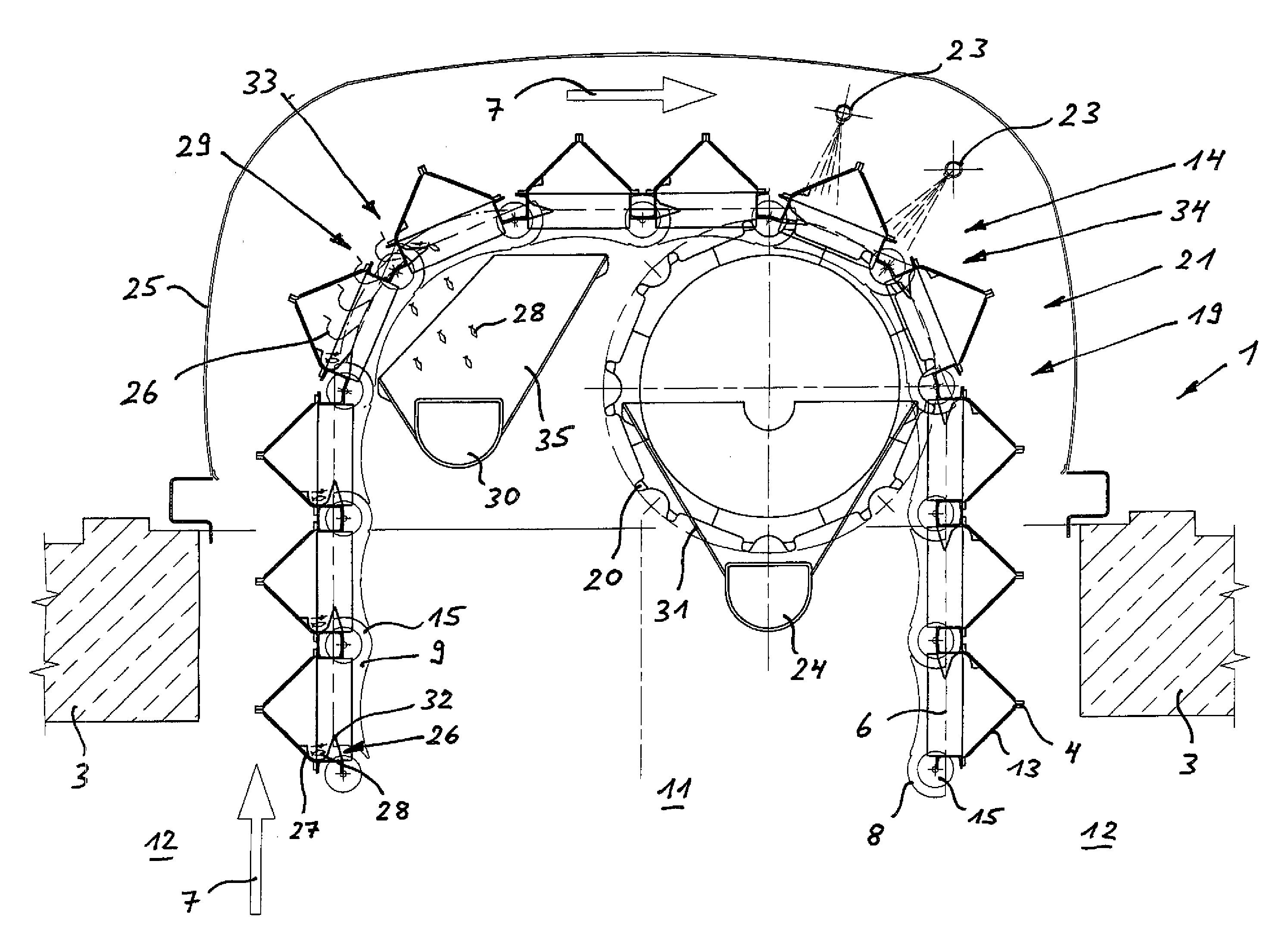
[0048]FIG. 4 shows a vertical section through the upper guidance zone of a first embodiment of a traveling band screen machine 1 of the invention with screen panels 4 that have a fish lifting channel 26 on the inflow side, i.e. the contaminated water side. The fish lifting channels 26 are arranged and constructed here such that in the upwardly moving screen panels 4, i.e. in the upwardly moving section 8 of the endless screen band 6, they are arranged at the lower end of the screen panel 4, in the upwardly moving screen panels 4 they form a collecting recess 27 filled is with liquid for aquatic animals 28 found in the respective screen panel 4 whereby, on movement of the endless screen band 6 with the screen panel 4, the liquid contained in the collecting recess and aquatic animals 28 caught therein are lifted out of the stream of liquid 5 in the direction of movement 7 of the endless screen band 6 and in the upper guidance zone of the endless screen band 6, in an emptying zone 29 o...


PUM

PropertyMeasurementUnit
Fractionaaaaaaaaaa
Fractionaaaaaaaaaa
Radiusaaaaaaaaaa

Abstract

A traveling band screen machine (1) is proposed with a careful fish return. To this end, the screen panels (4) each have a fish lifting channel (26) in which fishes (28) in a liquid-filled collecting recess (27) are lifted out of the stream of liquid and then emptied in the upper guidance zone (21) of the endless screen band (6) in an emptying zone (29) of the screen band machine (1) into a catch collecting drain (30) by tilting the screen panel (4) and the collecting recess (27) before the screen panel (4) reaches the cleaning zone (14) with the spray nozzles (23), in which debris deposited from the sluice channel on the screen panel (4) is cleaned off into the debris collecting drain (24).

Description

[0001]The invention relates to a traveling band screen machine for mechanically depositing and extracting solid components, solid bodies or solid matter from a stream of liquid flowing in a sluice channel, in particular a screen or filter rake for process water, cooling water or waste water streams or for use in sewage treatment plants or hydroelectric power stations or for use in a water supply channel of a power station cooling water intake system.[0002]Such traveling band screen machines comprise a plurality of screen panels that form a revolving endless screen band immersing into the stream of liquid, in which a plurality of screen panels that are juxtaposed and arranged consecutively in the direction of movement of the endless screen band, both in the downwardly moving section of the endless screen band and in the upwardly moving section of the endless screen band, respectively form a common screen surface in the sluice channel, wherein the direction of flow both for the downwa...

Claims


Application Information

Patent Timeline
IPC IPC(8): B01D33/333B01D33/50B01D33/70
CPCB01D33/333E02B1/006E02B8/026B01D33/50
Inventor HEIL, KLAUS
Owner PASSAVANT - GEIGER
Why Eureka
Try Eureka