
Group of three stator windings for a stator of an electric machine, a stator arrangement, a generator, and wind turbine

a technology of electric machines and stators, applied in windings, wind energy generation, mechanical energy handling, etc., can solve the problems of difficult mounting of traditional double layer windings, reduce the axial extent of winding heads, reduce the material of windings, and reduce the weight

Active Publication Date: 2012-01-10
FLENDER GMBH
View PDF14 Cites 12 Cited by
  • Summary
  • Abstract
  • Description
  • Claims
  • Application Information

AI Technical Summary

Benefits of technology

The present invention provides a stator winding design for electrical machines that reduces the consumption of copper and the size of the winding overhangs. The design includes three stator windings that do not require the removal of the first coil when inserting the last coil in a segmented stator. The winding heads of the stator windings are designed to not touch each other when mounted in adjacent slots. The invention also allows for a reduction in the axial dimension of the winding heads and the overall weight of the electric machine. The stator windings are pre-formed to minimize the length of the windings and the space they occupy in the stator. The winding heads are arranged to not touch each other when mounted in adjacent slots. The invention also includes a stator arrangement and a generator comprising the stator winding design.

Problems solved by technology

However, in electrical machines with a high number of poles and a small pole pitch the traditional double layer windings can be difficult to mount because an insertion of a last coil within dedicated slots require to temporarily lift a first coil out of the slots while completing the winding of the coil, so that the last coil can be inserted underneath the temporarily removed part of the first coil.

Method used


Image

  • Group of three stator windings for a stator of an electric machine, a stator arrangement, a generator, and wind turbine
  • Group of three stator windings for a stator of an electric machine, a stator arrangement, a generator, and wind turbine

Examples


Embodiment Construction

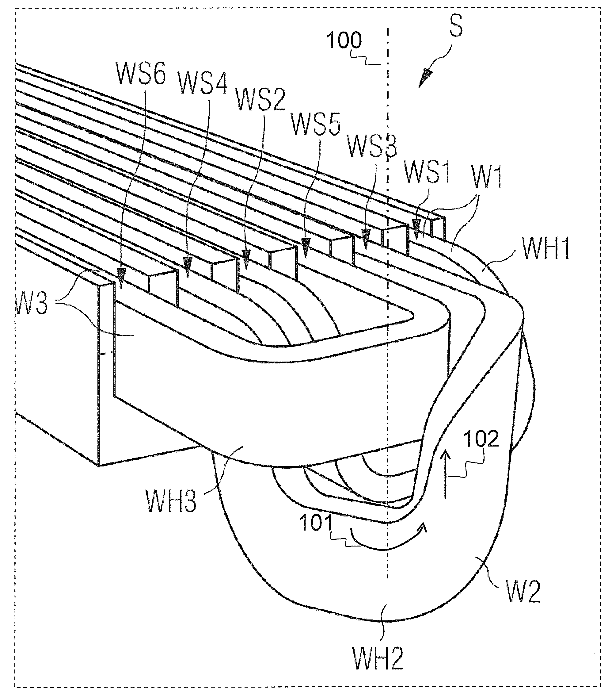
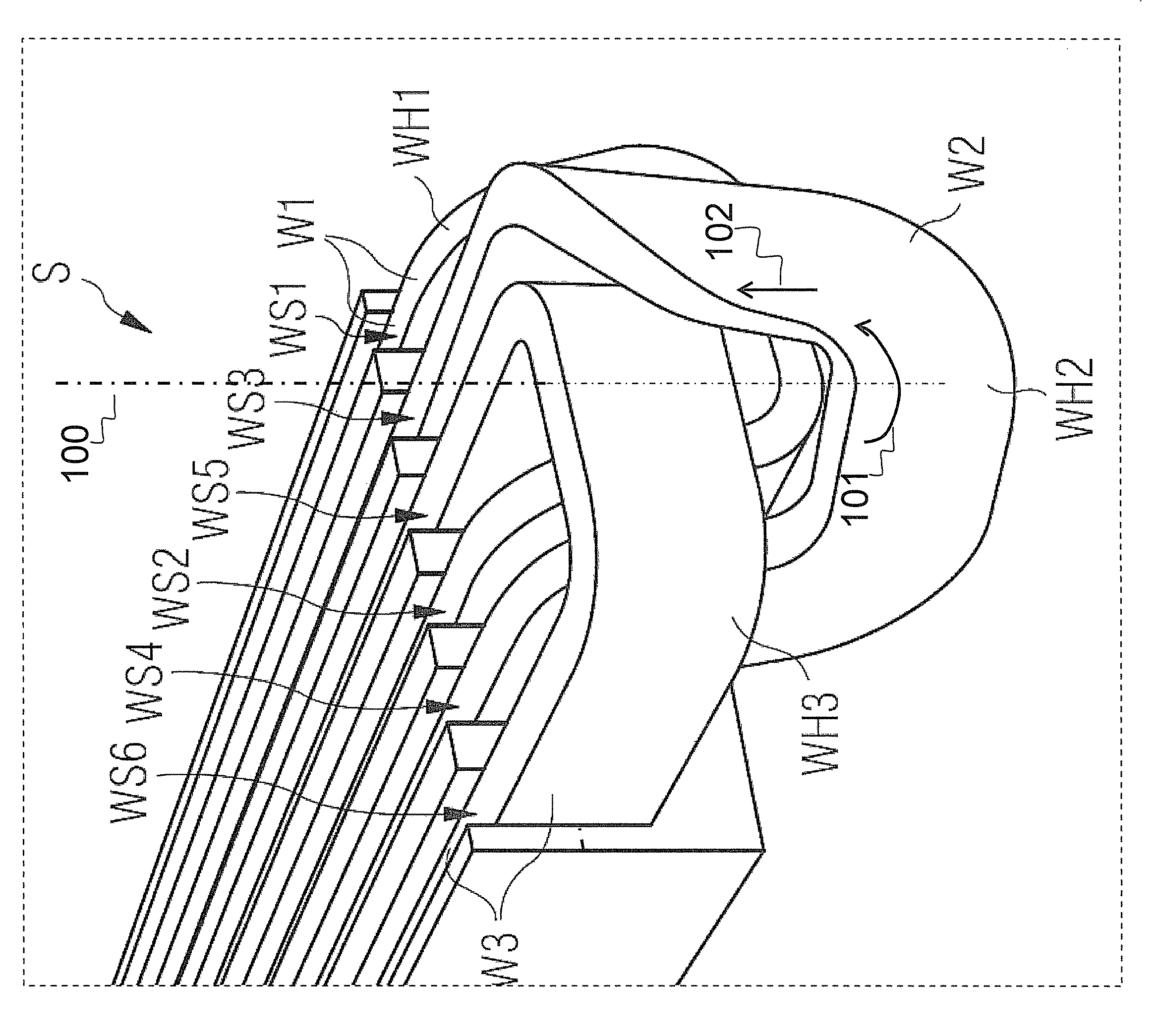
[0028]FIG. 1 shows a three-dimensional section of a stator S for a large conventional rotating electrical machine—especially a generator for a wind turbine. The complete stator S comprises a stator core SC and a large number of open-type radial winding slots WS1, WS2, . . . that are uniformly spaced around the circumference of the radially inner or outer surface of the stator core SC, depending whether the stator S is an inner or an outer stator of the electrical machine. Due to the large dimension of the stator S, the shown section of the stator S appears in FIG. 1 as a cuboid with substantially parallel winding slots WS1, WS2, . . . , WSx (x being a integer value of 1 to 6). This is acceptable as an approximation but it need to be understood that the adjacent winding slots WS1, WS2, . . . are not completely parallel planes regarding their slots, because the slots all are directed radially to a centre axis of the electrical machine. As a further approximation—or in other situations...


PUM


Abstract

In one aspect, a stator is provided having a first cylindrical surface with a plurality circumferentially spaced winding slots, each winding slot extending along an axial length of the first cylindrical surface and formed to embed a segment of a single stator winding, Each stator winding is pre-formed as a closed loop and two substantially parallel segments of each stator winding formed to be embedded in a first and a second winding slot of the stator, with the second winding slot being the third adjacent winding slot to the first winding slot. Each of the three stator windings has a first winding head segment leaving the winding slots in axial direction of the stator, the first winding head segment of a first winding of the three stator windings describing in space in parts a combination of a rotation about an axis and a translation along that axis.

Description

CROSS REFERENCE TO RELATED APPLICATIONS[0001]This application claims priority of European Patent Office application No. 08016467.6 EP filed Sep. 18, 2008, which is incorporated by reference herein in its entirety.FIELD OF INVENTION[0002]The invention relates to a group of three stator windings for a stator of an electric machine. The invention concerns also a stator arrangement comprising such stator windings, a generator—e.g. a direct drive generator for a wind turbine—comprising such a stator as well as a wind turbine comprising such a generator.BACKGROUND OF INVENTION[0003]In large electrical machines or generators it is common to use a so called double-layer winding. This winding type has the benefit that all coils are identical and the coils are easy to manufacture.SUMMARY OF INVENTION[0004]However, in electrical machines with a high number of poles and a small pole pitch the traditional double layer windings can be difficult to mount because an insertion of a last coil within ...

Claims


Application Information

Patent Timeline
Patent Type & Authority Patents(United States)
IPC IPC(8): H02K1/00H02K21/00H02K19/00H02K17/00H02K3/00H02K23/26
CPCH02K3/12H02K15/063Y02E10/725H02K7/1838H02K2213/12Y02E10/72
Inventor STIESDAL, HENRIK
Owner FLENDER GMBH
Learn More