Rotary vacuum apparatus for air screen

a vacuum apparatus and air filter technology, applied in the direction of auxillary pretreatment, separation process, filtration separation, etc., can solve the problems of reducing the vacuum condition, and reducing the cooling efficiency, so as to reduce the vacuum loss and dissipation, improve the vacuum condition, and reduce the effect of vacuum loss

Active Publication Date: 2012-01-17
BLUE LEAF I P INC
View PDF24 Cites 19 Cited by
  • Summary
  • Abstract
  • Description
  • Claims
  • Application Information

AI Technical Summary

Benefits of technology

[0009]What is disclosed is a rotary vacuum cleaning apparatus for an air filter screen for agricultural and other machines which more effectively filters air flow therethrough, without the shortcomings and disadvantages set forth above.
[0012]As another preferred aspect of the invention, the apparatus includes an elongate plate supported for rotation about the rotational axis with the vacuum arm, in at least substantially parallel opposing relation thereto in proximity to an opposite surface of the air filter screen from the vacuum arm, for increasing effectiveness of vacuum conditions present in the orifices for removing contaminants from the screen.
[0013]According to still another preferred aspect of the invention, at least one of the arm portions includes at least one brush extending longitudinally therealong, for improving contaminant removal, by limiting vacuum loss and dissipation, and for operation in cooperation with a knife disposed on the screen and configured for cleaning debris and larger elements of contamination, such as leaves of plants and the like, from the brush. Further in this regard, the knife can include serrations or fingers for breaking up the larger elements for facilitating induction into the vacuum arm. Preferably, the brush is supported so as to move in close proximity to the screen surface, without actually contacting the surface, and the serrations or fingers, are oriented so as to extend in the direction of rotation of the brush, so as to be non-aggressive, for achieving good cleaning of the brush and break up of larger contaminants, without excessive wear and other problems.

Problems solved by technology

Often, the air flow requirements are greatest while the levels of airborne contaminants are high, creating an increased potential for the deposition and buildup of the contaminants in small interstices and passages in screens and grills covering and protecting the heat dissipating devices, and in the devices themselves, which can reduce the cooling efficiency thereof so as to require periodically stopping the operation of the machine and cleaning the heat dissipating devices and / or screens or grills.
An observed shortcoming of rotary air filters of this type, however, is the requirement of relatively large perforations in the structure which can allow relatively large amounts of foreign material into the interior thereof, some of which foreign material can pass beyond the discharge structure and collect on the radiators, engine, and other functional elements to an undesirable extent.
Another observed shortcoming with this and other rotary screens is wear at the seal interface between the rotating air filter and the surrounding fixed structure, which can create openings through which contaminants can pass.
However, the known scraper and plow devices are necessarily of rigid construction such that, if biased or urged against a filter screen to an effective extent, would likely stretch and deform the screen over time thus lessening the cleaning effect achieved.
Also, such devices, if allowed to prolongedly contact a mesh screen or the like, can rub or wear through the screen, thus necessitating replacing or repairing the screen on a more frequent than desirable basis.
Further, if the leading edge of the scraper or plow wears, it can form an edge that can tear and damage the filter screen.
Some of the disclosed scrapers and plows also have relatively complex geometric shapes, making them costly to make.
Still further devices utilize vacuum arms rotatable over a screen for removing contaminants, however, many of these devices utilize small vacuum orifices that would likely become clogged with larger elements of trash and debris, such as corn leaves and the like, and some are asymmetrical such that vacuum is provided to only one arm, requiring an opposite counterbalance weight, which is otherwise useless.

Method used


Image

  • Rotary vacuum apparatus for air screen
  • Rotary vacuum apparatus for air screen
  • Rotary vacuum apparatus for air screen

Examples


Embodiment Construction

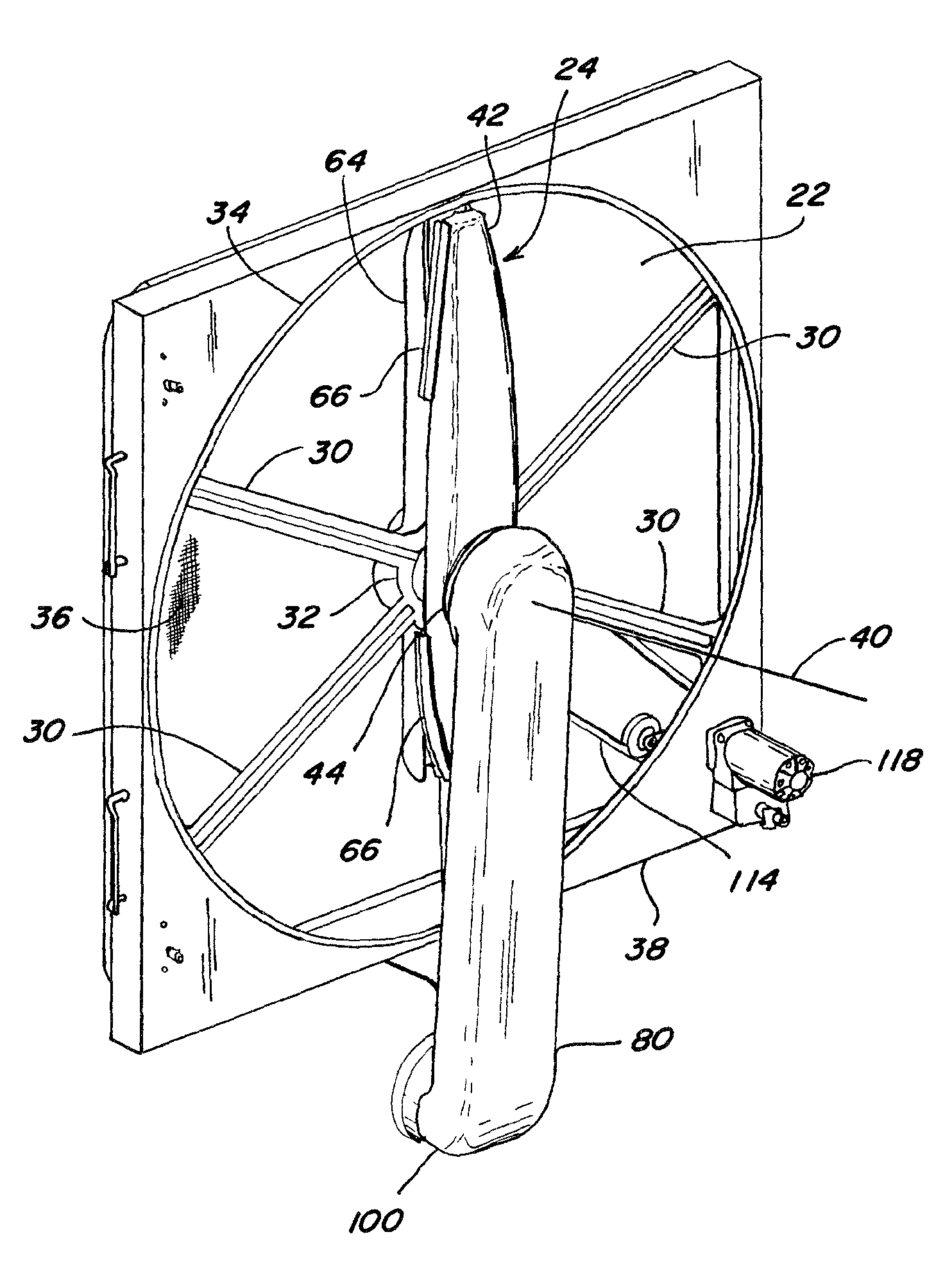
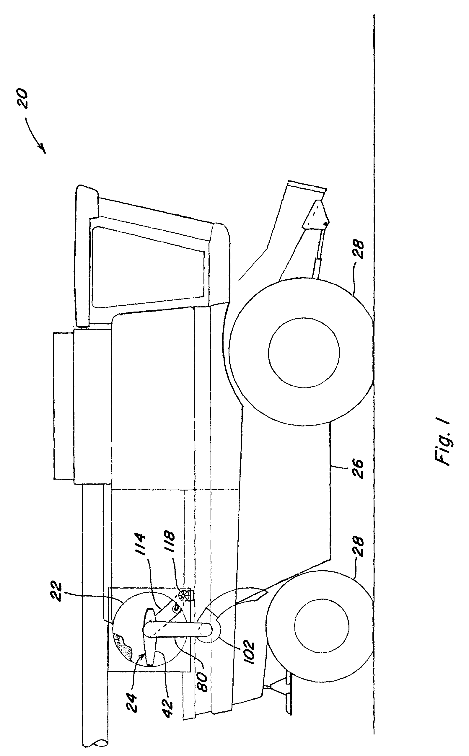
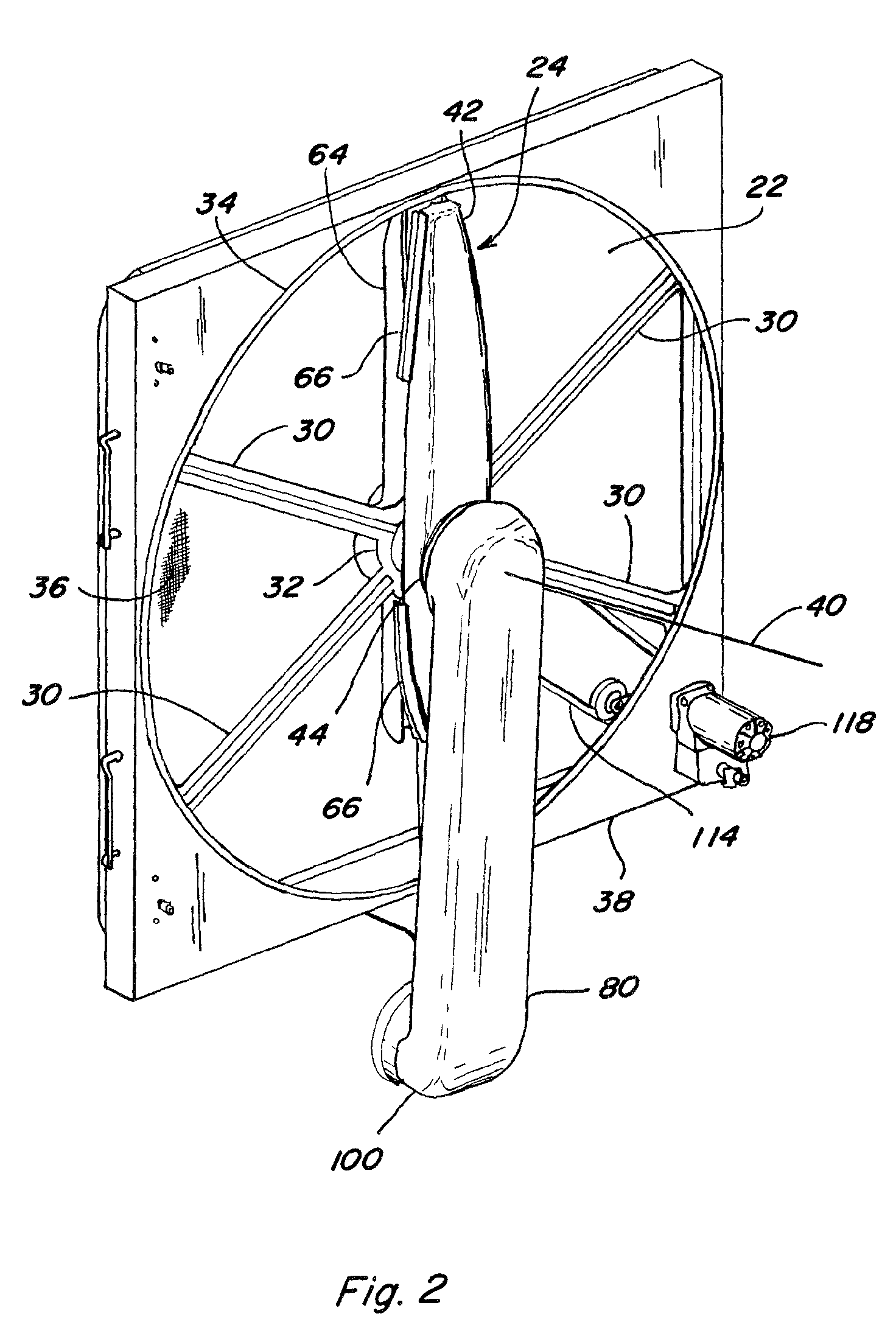
[0027]Referring now to the drawings, in FIG. 1, a representative work machine, which is an agricultural combine harvester 20, is shown including an air filter screen assembly 22, and an associated rotary vacuum cleaning apparatus 24 constructed and operable according to the teachings of the present invention, for cleaning screen assembly 22. Harvester 20 includes a mobile frame 26 supported by a plurality of wheels 28 for movement over the ground for harvesting crops from a field using a header (not shown) mounted to the front of harvester 20, in the well-known manner. Harvester 20 includes an internal combustion engine (also not shown) for providing motive power to wheels 28, and a hydraulic circuit including a pump (not shown) driven by the engine, for propulsion, and also powering various subsystems of harvester 20, again, in the well-known manner. Harvester 20 includes at least one heat exchanger and / or radiator for dissipating heat from elements of various of the subsystems of ...


PUM

PropertyMeasurementUnit
distanceaaaaaaaaaa
radial distanceaaaaaaaaaa
rotationaaaaaaaaaa

Abstract

A vacuum apparatus rotatable about an axis through a filter screen for continually removing contaminants, which utilizes an asymmetrical vacuum arm supported by a center hub, and large longitudinally extending asymmetrical vacuum orifices in portions of the arm on opposite sides of the hub, operable for removing large elements of debris, trash and the like from the screen. One of the arm portions cleans a radial outer region of the screen, and the other cleans an inner region, the arm portions being generally even in mass for balance. A knife disposed on the screen cleans and cooperates with a brush on the arm for breaking up larger elements of trash. The arm is also manually removable via a snap together vacuum seal joint, for service and cleaning.

Description

[0001]This application claims the benefit of U.S. Provisional Application No. 61 / 031,618, filed Feb. 26, 2008.TECHNICAL FIELD[0002]The present invention generally relates to a rotary vacuum apparatus for an air screen for filtering air flow to heat dissipating devices used for cooling functional elements of work machines such as harvesters for cotton, grains, and corn, construction machines, forestry machines, mining machines, and the like, and, more particularly, to a modular rotary vacuum apparatus having an improved capability for handling larger elements of trash, with less screen wear, and other advantages, including ease of disassembly and cleaning.BACKGROUND ART[0003]U.S. Provisional Application No. 61 / 031,618, filed Feb. 26, 2008, is incorporated herein in its entirety by reference.[0004]Modern work machines, particularly agricultural harvesters for plants such as cotton, grains, and corn, are typically operated under hot, dry environmental conditions wherein considerable le...

Claims


Application Information

Patent Timeline
Patent Type & Authority Patents(United States)
IPC IPC(8): B01D50/00
CPCB01D46/0065B01D46/10F01P11/12B01D2273/28B01D46/681B01D46/682
Inventor JOHNSON, BRIAN K.TAMAMIDIS, PANOSSCOTT, DAVID A.
Owner BLUE LEAF I P INC
Why Eureka
Try Eureka