Sintered fiber filter
a fiber filter and fiber filter technology, applied in the direction of filtration separation, separation processes, manufacturing tools, etc., can solve the problems of adversely reducing (restricting) the flow of process fluids, and achieve the effects of low pressure drop during operation, high efficiency removal of particulates, and low packing density
- Summary
- Abstract
- Description
- Claims
- Application Information
AI Technical Summary
Benefits of technology
Problems solved by technology
Method used
Image
Examples
example 1
[0061]A cylindrical filter element was made using metal fibers as described in U.S. Pat. No. 7,045,219 (N. V. Bekaert S. A., Belgium—Bekinox SF 1.5 μm / 316 LV Z60). The fibers were 316L stainless steel, about 1.5 microns in diameter and nominally about 75 to about 100 microns long. 22 g of metal fiber was measured into a glass beaker. 1000 mL deionized water was measured into a plastic Tri-Pore beaker, and 200 mL deionized water was measured into a separate plastic Tri-Pore beaker. The 22 g of fiber was mixed into the 1000 mL deionized water and stirred with a glass stirring rod until thoroughly mixed. The fiber / water mixture was poured into and compressed using a forming fixture as illustrated in FIG. 5, using a vibrator table and vacuum, as described in detail above with reference to operation of the fixture of FIG. 5. The 200 mL additional deionized water was used to clean remaining fiber into the tooling before compression. Compression yielded a green fiber tube approximately 3.2...
example 2
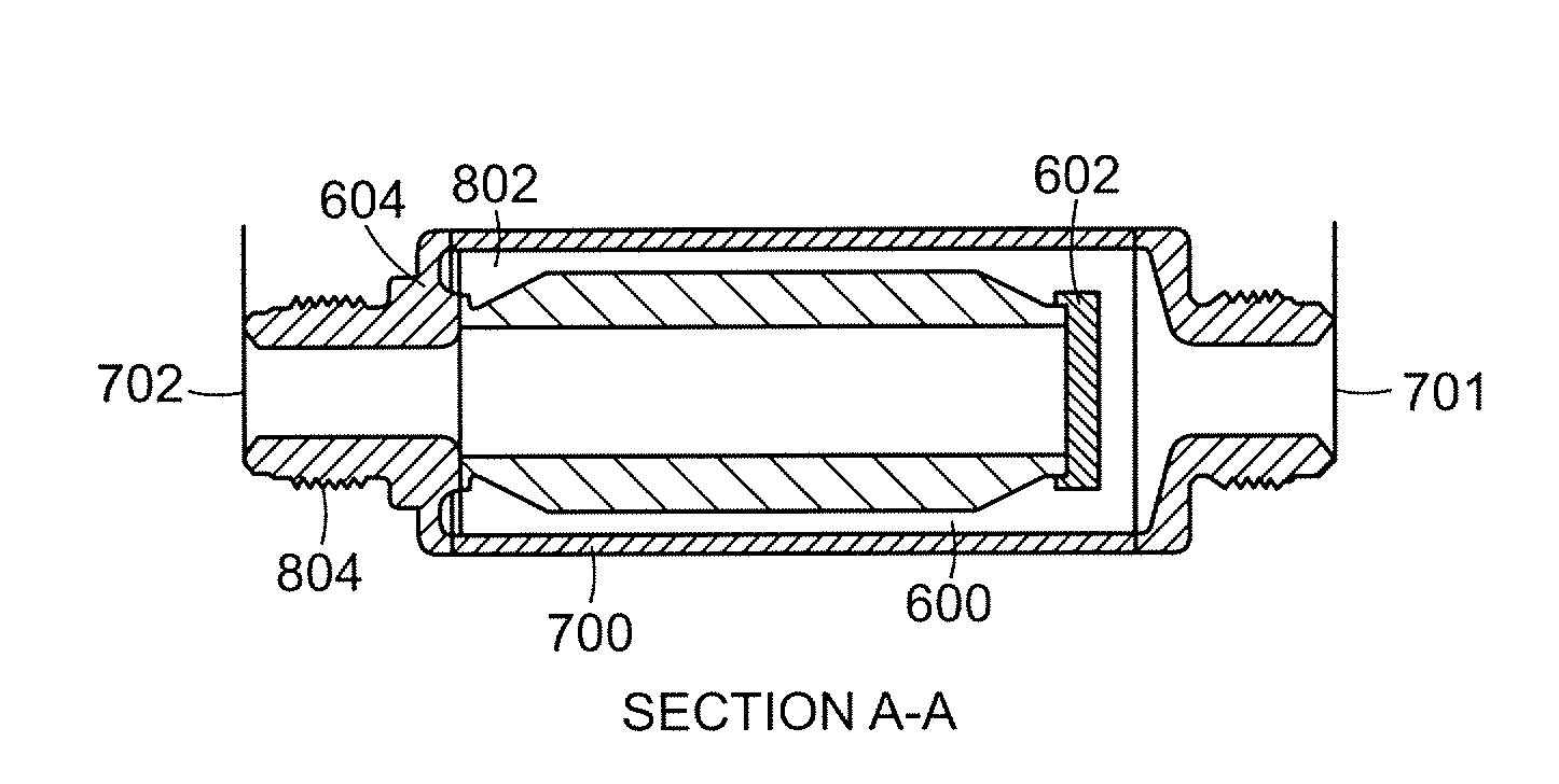
[0062]The filter element made according to Example 1 was then subsequently welded and assembled to achieve a filter as shown in FIGS. 6 and 8. This filter was subsequently tested to obtain the pressure drop data and particle collection efficiency data shown in FIGS. 10 and 11, respectively.
[0063]A filter particle loading test was performed on a filter made according to Example 1. The air flow rate was 100 SLM, the particle size was 0.07 microns, which was determined to represent the most penetrating particle size, the challenge concentration was 20,000 particles per cubic centimeter, and the initial LRV was 7.3. The total particle challenge for this test was five trillion particles, and the final LRV was greater than 9. The initial pressure drop was 1.8 psid and the final pressure drop was 2.1 psid, which represented an increase of 0.3 psid or 16%. These results demonstrate that the filter pressure drop increased only a modest amount while the filter was subjected to a high degree o...
example 3
[0064]A cylindrical filter element was made using metal fibers as described in U.S. Pat. No. 7,045,219 (N. V. Bekaert S. A., Belgium—Bekinox SF 1.5 μm / 316 LV Z60). The fibers were 316L stainless steel, about 1.5 microns in diameter and nominally about 75 to about 100 microns long. 44 g of metal fiber was measured into a glass beaker. 1500 mL deionized water was measured into a plastic Tri-Pore beaker, and 200 mL deionized water was measured into a separate plastic Tri-Pore beaker. The 44 g of fiber was mixed into the 1500 mL deionized water and stirred with a glass stirring rod until thoroughly mixed. The fiber / water mixture was poured into and compressed using a forming fixture as illustrated in FIG. 5, using vacuum, as described in detail above with reference to operation of the fixture of FIG. 5. The 200 mL additional deionized water was used to clean remaining fiber into the tooling before compression. Compression yielded a green fiber tube approximately 3.2 inches long.
[0065]Th...
PUM
| Property | Measurement | Unit |
|---|---|---|
| thickness | aaaaa | aaaaa |
| thickness | aaaaa | aaaaa |
| thickness | aaaaa | aaaaa |
Abstract
Description
Claims
Application Information
 - R&D
- Intellectual Property
- Life Sciences
- Materials
- Tech Scout
- Unparalleled Data Quality
- Higher Quality Content
- 60% Fewer Hallucinations
Browse by: Latest US Patents, China's latest patents, Technical Efficacy Thesaurus, Application Domain, Technology Topic, Popular Technical Reports.
© 2025 PatSnap. All rights reserved.Legal|Privacy policy|Modern Slavery Act Transparency Statement|Sitemap|About US| Contact US: help@patsnap.com


