Sintered fiber filter

a fiber filter and fiber filter technology, applied in the direction of filtration separation, separation processes, manufacturing tools, etc., can solve the problems of adversely reducing (restricting) the flow of process fluids, and achieve the effects of low pressure drop during operation, high efficiency removal of particulates, and low packing density

Active Publication Date: 2009-07-02
MOTT CORP
View PDF21 Cites 27 Cited by
  • Summary
  • Abstract
  • Description
  • Claims
  • Application Information

AI Technical Summary

Benefits of technology

[0008]Described herein are sintered fiber filters. In certain embodiments, the filters provide high efficiency removal of particulates and / or low pressure drop during operation, and are useful in applications such as semiconductor processing. The shape of at least a portion of the individual fibers (e.g., metal fibers) that make up the filter have a three-dimensional aspect, which allows for a low packing density and high porosity filtration media. Such low density / high porosity promotes a low pressure drop across the resultant filter formed from the media. Varying the degree of compression and / or varying the quantity of fibers during molding of the filter allows for control of the filtration rating, or particle capture efficiency and differential pressure of the resultant filter. In certain embodiments, the filter has a cylindrical or tube-like shape, in some instances having tapered ends of higher density that allow for welding, e.g., to a metal end cap and / or filter assembly. Methods of making such filters, for example, using axial pressing, are also disclosed.

Problems solved by technology

This is because some process fluids, such as gases produced from vaporization of liquid sources, have limited abilities to pressurize the gas system; thus, filters with higher pressure drops could adversely reduce (restrict) the flow of process fluids.
Furthermore, in a typical high purity fluid supply system each component contributes to the overall pressure drop across the system.

Method used


Image

  • Sintered fiber filter
  • Sintered fiber filter
  • Sintered fiber filter

Examples


example 1

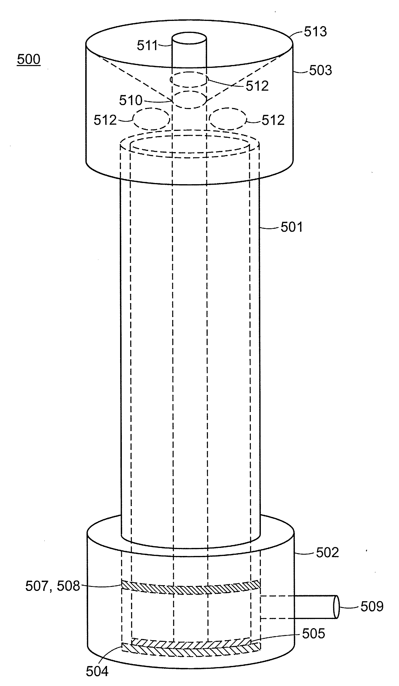
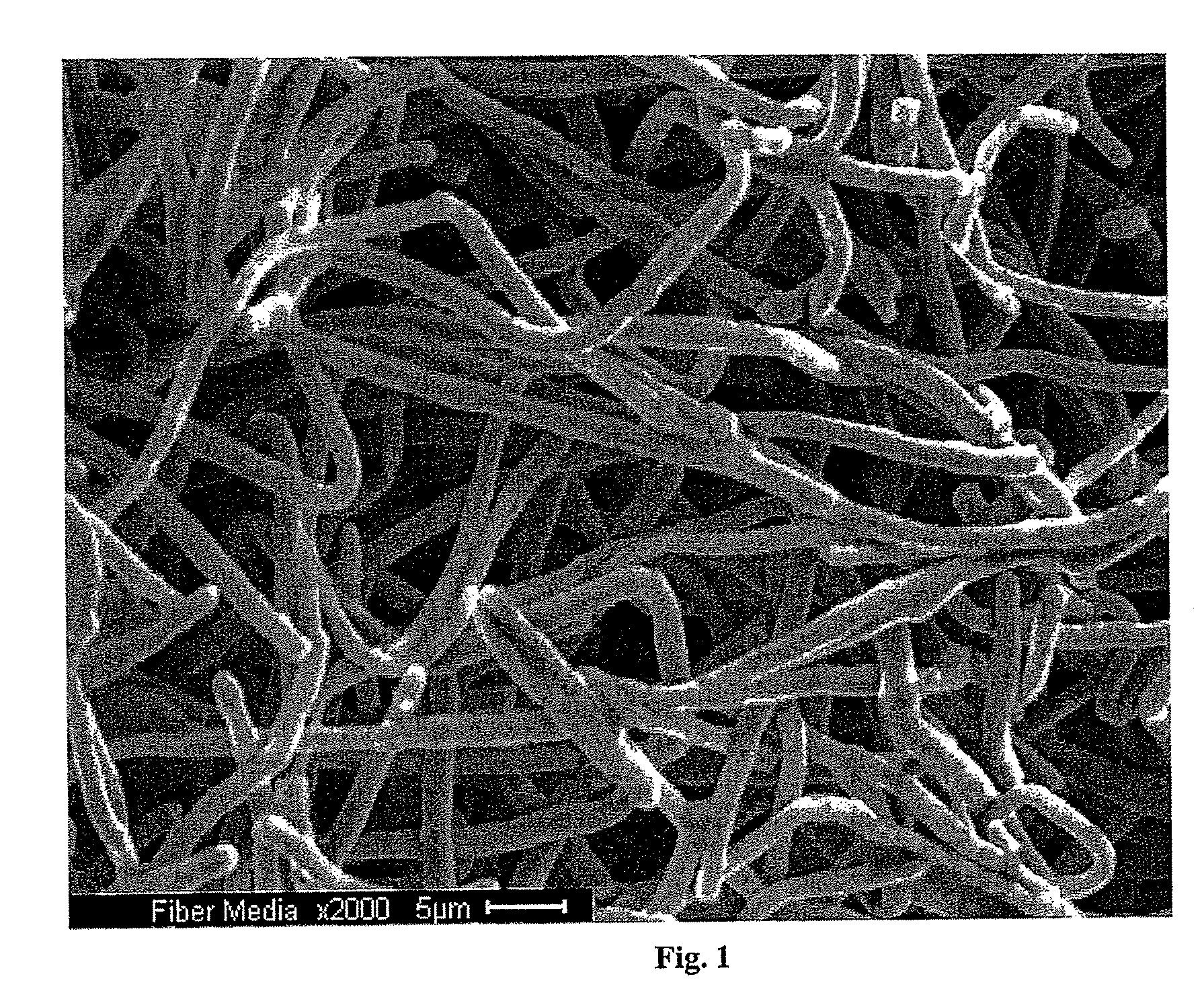
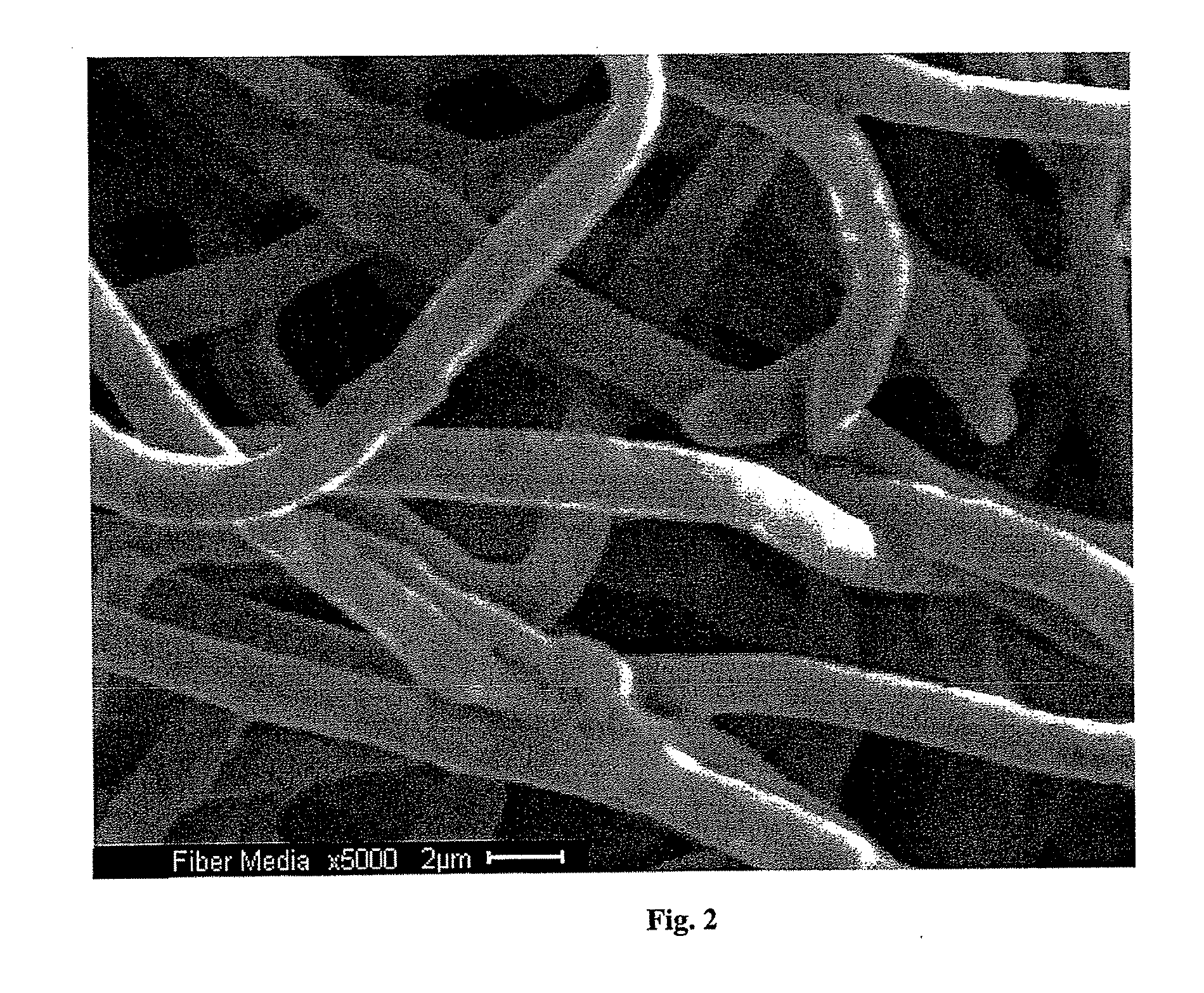
[0061]A cylindrical filter element was made using metal fibers as described in U.S. Pat. No. 7,045,219 (N.V. Bekaert S.A., Belgium—Bekinox SF 1.5 μm / 316 LV Z60). The fibers were 316L stainless steel, about 1.5 microns in diameter and nominally about 75 to about 100 microns long. 22 g of metal fiber was measured into a glass beaker. 1000 mL deionized water was measured into a plastic Tri-Pore beaker, and 200 mL deionized water was measured into a separate plastic Tri-Pore beaker. The 22 g of fiber was mixed into the 1000 mL deionized water and stirred with a glass stirring rod until thoroughly mixed. The fiber / water mixture was poured into and compressed using a forming fixture as illustrated in FIG. 5, using a vibrator table and vacuum, as described in detail above with reference to operation of the fixture of FIG. 5. The 200 mL additional deionized water was used to clean remaining fiber into the tooling before compression. Compression yielded a green fiber tube approximately 3.2 i...

example 2

[0062]The filter element made according to Example 1 was then subsequently welded and assembled to achieve a filter as shown in FIGS. 6 and 8. This filter was subsequently tested to obtain the pressure drop data and particle collection efficiency data shown in FIGS. 10 and 11, respectively.

[0063]A filter particle loading test was performed on a filter made according to Example 1. The air flow rate was 100 SLM, the particle size was 0.07 microns, which was determined to represent the most penetrating particle size, the challenge concentration was 20,000 particles per cubic centimeter, and the initial LRV was 7.3. The total particle challenge for this test was five trillion particles, and the final LRV was greater than 9. The initial pressure drop was 1.8 psid and the final pressure drop was 2.1 psid, which represented an increase of 0.3 psid or 16%. These results demonstrate that the filter pressure drop increased only a modest amount while the filter was subjected to a high degree o...

example 3

[0064]A cylindrical filter element was made using metal fibers as described in U.S. Pat. No. 7,045,219 (N.V. Bekaert S.A., Belgium—Bekinox SF 1.5 μm / 316 LV Z60). The fibers were 316L stainless steel, about 1.5 microns in diameter and nominally about 75 to about 100 microns long. 44 g of metal fiber was measured into a glass beaker. 1500 mL deionized water was measured into a plastic Tri-Pore beaker, and 200 mL deionized water was measured into a separate plastic Tri-Pore beaker. The 44 g of fiber was mixed into the 1500 mL deionized water and stirred with a glass stirring rod until thoroughly mixed. The fiber / water mixture was poured into and compressed using a forming fixture as illustrated in FIG. 5, using vacuum, as described in detail above with reference to operation of the fixture of FIG. 5. The 200 mL additional deionized water was used to clean remaining fiber into the tooling before compression. Compression yielded a green fiber tube approximately 3.2 inches long.

[0065]The ...


PUM

PropertyMeasurementUnit
thicknessaaaaaaaaaa
thicknessaaaaaaaaaa
thicknessaaaaaaaaaa

Abstract

Sintered fiber filters are provided that can afford high particle capture efficiency and/or low pressure drop during operation, and are useful in applications such as semiconductor processing. The shape of at least a portion of the individual fibers (e.g., metal fibers) used to make the filter have a three-dimensional aspect, which allows for a low packing density and high porosity filtration media. Certain filters have a cylindrical or tube-like shape with tapered ends of higher density. Methods of making such filters, for example, using axial pressing, are also described.

Description

CROSS-REFERENCE TO RELATED APPLICATIONS[0001]This application claims priority to U.S. Provisional Application No. 60 / 982,328, filed Oct. 24, 2007, which is incorporated herein by reference.BACKGROUND[0002]1. Technical Field[0003]The field relates to sintered metal filters and methods of making and using the same to filter fluids, including in applications requiring high efficiency filtration and / or a low pressure drop across the filter.[0004]2. Description of Related Art[0005]Porous metal filters, for example, made from metal powder or metal fiber, are widely used in a variety of applications. For instance, in semiconductor manufacturing and other industrial processes, a very clean environment often is required to produce sensitive products. For example, in the electronics industry, inline filters are often used to filter particulate matter from fluids in order to reduce the introduction of such particulate matter into the manufacturing process for semiconductors, thereby reducing t...

Claims


Application Information

Patent Timeline
Patent Type & Authority Applications(United States)
IPC IPC(8): C04B35/76B01D39/20C04B35/645B01D46/42B28B1/087B28B1/52
CPCB22F7/002B01D39/2044B01D35/30B01D39/20B01D46/00
Inventor BURGESS, DEREKWHITE, WAYNE F.ROMANO, ALFRED M.PFLUGBEIL, TODD W.BALAZY, RICHARD D.RUBOW, KENNETH L.ROSENBERGER, JOHN E.
Owner MOTT CORP
Why Eureka
Try Eureka