Micro actuator
a micro actuator and actuator technology, applied in the field of actuators, can solve the problems of poor usability and large size of linear actuators, and achieve the effects of reducing the difference between the stroke length of the spline nut and the overall length of the actuator, reducing the number of components, and reducing the size of the actuator
- Summary
- Abstract
- Description
- Claims
- Application Information
AI Technical Summary
Benefits of technology
Problems solved by technology
Method used
Image
Examples
first embodiment
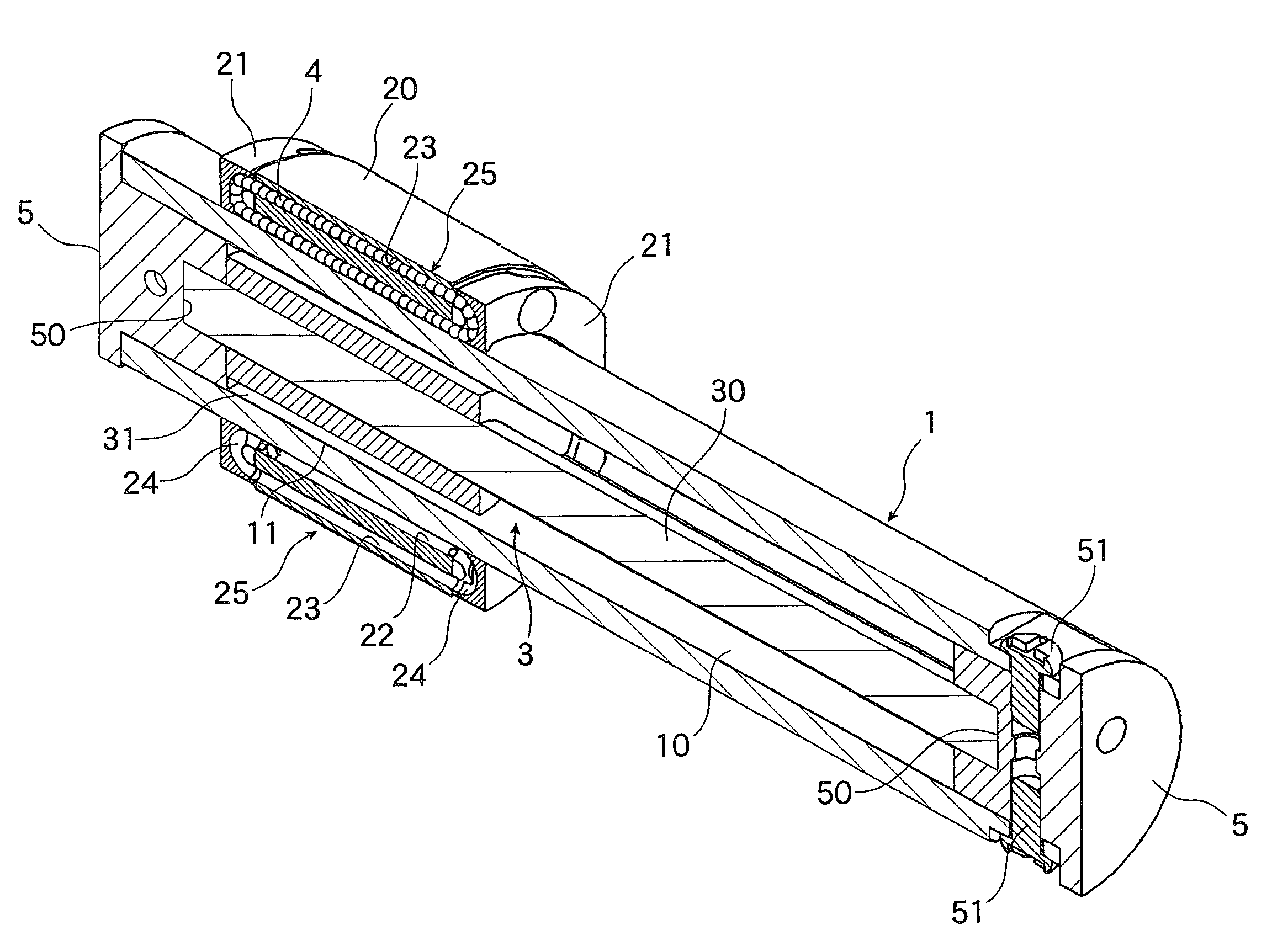
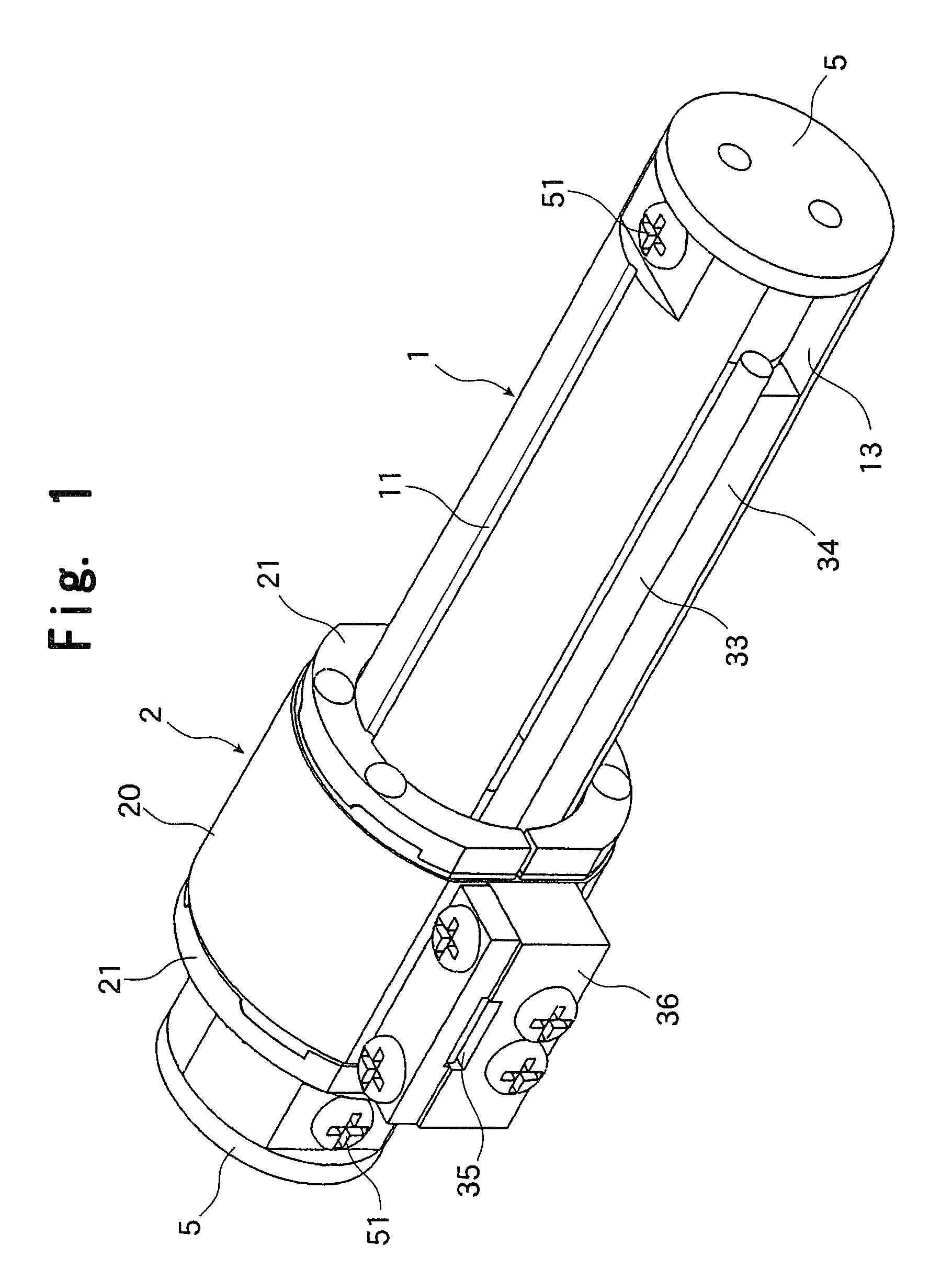
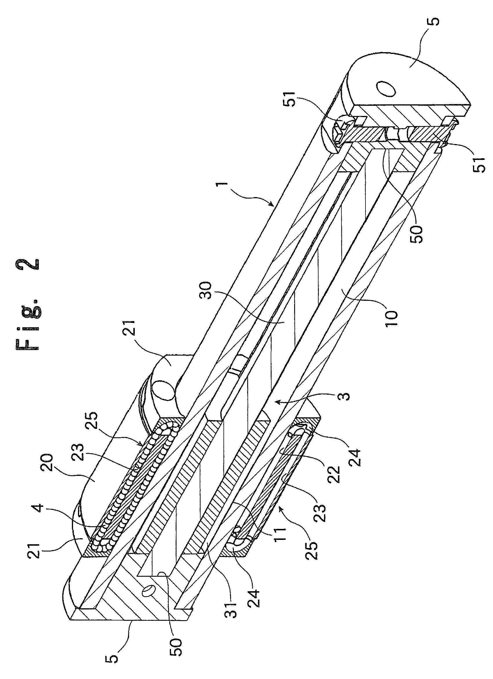
[0022]FIGS. 1 through 4 show a micro actuator according to the present invention. FIG. 1 is a general perspective view, FIG. 2 is a vertically cutaway longitudinal perspective view, FIG. 3 is a horizontally cutaway longitudinal perspective view, and FIG. 4 is a perspective view cut away perpendicularly to the longitudinal direction at the center of a spline nut described below. This micro actuator is equipped with a spline shaft 1 having a hollow part 10 and formed in a substantially cylindrical configuration, and a spline nut 2 fit-engaged with the outer side of the spline shaft 1 through the intermediation of a large number of balls, and is capable of reciprocating the spline nut 2 in the axial direction of the spline shaft 1 by utilizing thrust generated by a linear motor 3 accommodated in the hollow part 10 of the spline shaft 1.
[0023]The spline shaft 1 has the hollow part 10 and is formed in a cylindrical configuration, with the outer peripheral surface thereof having two ball ...
second embodiment
[0036]FIGS. 5 and 6 show a micro actuator according to the present invention, in which, as stated above, only one slit opening 14 is formed for the spline shaft 1. FIG. 5 is a general perspective view, and FIG. 6 is a general perspective view as seen from the opposite side.
[0037]In FIG. 5, the slit opening 14 extending in the axial direction is provided at one position in the outer peripheral surface of the spline shaft 1, and the spline nut 2 is connected with the forcer 31 constituting the linear motor 3 through the slit opening 14.
[0038]Further, as shown in FIG. 6, a flat surface 60 is formed on the outer peripheral surface of the spline shaft at position out of phase with respect to the slit opening by 180°, and a tape-like linear scale 61 is attached to the flat surface 60. As in the first embodiment, the linear scale 61 is formed as a magnet scale. A reading head (not shown) is fixed to the spline nut 2 at a position opposed to the linear scale 61; when the spline nut 2 moves ...
third embodiment
[0041]Next, FIG. 7 shows a micro actuator according to the present invention.
[0042]In the micro actuator of the third embodiment, in order to enhance the thrust exerted by the linear motor 3, a plurality of sets of exciting coils, of which each three exciting coils of the three phases constitutes one set, are mounted on a forcer 37 loosely fit-engaged with the magnet rod 30. Thus, the forcer 37 is formed longer in the axial direction of the magnet rod 30 as compared with the forcer 31 of the second embodiment. Further, in order to reliably support the elongated forcer 37, a pair of spline nuts 2 are fit-engaged with the spline shaft 1 at an axial interval, with the spline nuts 2 being respectively connected with the longitudinal ends of the forcer 37. That is, the pair of spline nuts 2 are connected to each other through the intermediation of the forcer 37; when the linear motor 3 is driven, the spline shaft 1 retaining the magnet rod 30 moves relative to the spline nuts 2, with the...
PUM
 Abstract
Description
Claims
Application Information
 - R&D
- Intellectual Property
- Life Sciences
- Materials
- Tech Scout
- Unparalleled Data Quality
- Higher Quality Content
- 60% Fewer Hallucinations
Browse by: Latest US Patents, China's latest patents, Technical Efficacy Thesaurus, Application Domain, Technology Topic, Popular Technical Reports.
© 2025 PatSnap. All rights reserved.Legal|Privacy policy|Modern Slavery Act Transparency Statement|Sitemap|About US| Contact US: help@patsnap.com


