Low-profile upholstery clip for attaching a bead to a foam substrate

a foam substrate and low-profile technology, applied in the field of low-profile upholstery clips, can solve the problems of difficult repair of permanent joints, difficult to create permanent joints, and fabric will tend to billow or “tents”, and achieve the effects of high resistance, high resistance, and easy bead installation

Active Publication Date: 2012-01-24
HOPE GLOBAL DIV OF NFA
View PDF138 Cites 68 Cited by
  • Summary
  • Abstract
  • Description
  • Claims
  • Application Information

AI Technical Summary

Benefits of technology

[0014]This invention overcomes the disadvantages of the prior art by providing a low-profile clip adapted to secure a listing bead to a foam substrate. Such a low-profile clip employs a novel geometry and is constructed from a material that affords resilience, durability, high resistance to a wide range of temperatures during field use and seat assembly and ease of bead installation with high pull-out strength. In an illustrative embodiment, the clip includes a base and a pair of legs extending upwardly from the base and defining therebetween a central region constructed and arrangement to capture the listing bead. Each of the legs extends upwardly from the base to a top barb that defines a gap narrower than central region. In this embodiment, the legs each extend outwardly and vertically upwardly from the base at a first angle of approximately 80 to 85 degrees, and relative to the horizontal plane of the base to each of the respective barbs at a second angle, with respect to a line parallel to the base of approximately 88 to 90 degrees. Each of the legs has an approximate thickness taken along a direction of the parallel line of between approximately 1.0 and 2.0 millimeters. In this manner the clip exhibits high performance while defining an overall height from tops of the legs to a bottom of the base of approximately ten millimeters or less making the clip particularly desirable for use in modern, thinner foam substrates.
[0015]In an illustrative embodiment, each of the barbs are free of upward extensions and define each of a pair of sloping top surfaces directed downwardly toward the gap and the base. Notably, the bottom surface of each of the barbs defines an angle that is approximately the same as an angle of an engaging surface of the listing bead. The clip is constructed from a blended polycarbonate material, which provides good performance characteristics and exhibits good chemical adhesion to liquid foam.

Problems solved by technology

Otherwise, the fabric will tend to billow or “tent” at these non-planar surface features.
Clearly, this permanent joint is difficult to repair if needed and requires significant skill to create in the first place.
In addition, this method of seat cover attachment leads to the development of injuries, such as carpal tunnel syndrome in employees who operate the hog ring tool over an extended period of time.
Finally, the use of metal components may be undesirable where the seat includes electrical heating elements due to the metal's predisposition to conduct both heat and electricity.
This approach is reliable, but expensive, in terms of material wasted and consumed to attain a secure fit.
Many polymeric materials, however, are not capable of enduring the requisite range of operating temperatures to which a vehicle interior and the underlying clips may be exposed—for example, during molding and roll-forming of the foam.
It should be noted also, that the process of inserting clips into a foam mold cavity, used for example to form seat parts, is typically a manual operation that is time-consuming, labor-intensive and sometimes subject to inaccurate placement.
This process contains inherent inefficiencies that the worker cannot fully overcome.
Moreover, loosely packing ganged groups of clips, connected by intermediate connecting segments further complicates handling.
It has been found that a loosely packed supply of ganged clips generally assumes a “bird's nest” entanglement that is extremely difficult to unravel.
However, thinner foam layers cause conventional height clips (typically 13 millimeters, or higher, from base to top) may protrude visibly from the foam layer when upholstered, and / or become noticeable as a hard, pointy protuberance to a seated individual—particularly an individual of heightened body weight.
The materials, dimensions and geometry employed for the clip may not accommodate a smaller-length leg.

Method used


Image

  • Low-profile upholstery clip for attaching a bead to a foam substrate
  • Low-profile upholstery clip for attaching a bead to a foam substrate
  • Low-profile upholstery clip for attaching a bead to a foam substrate

Examples


Embodiment Construction

I. Festooned Clip Arrangements

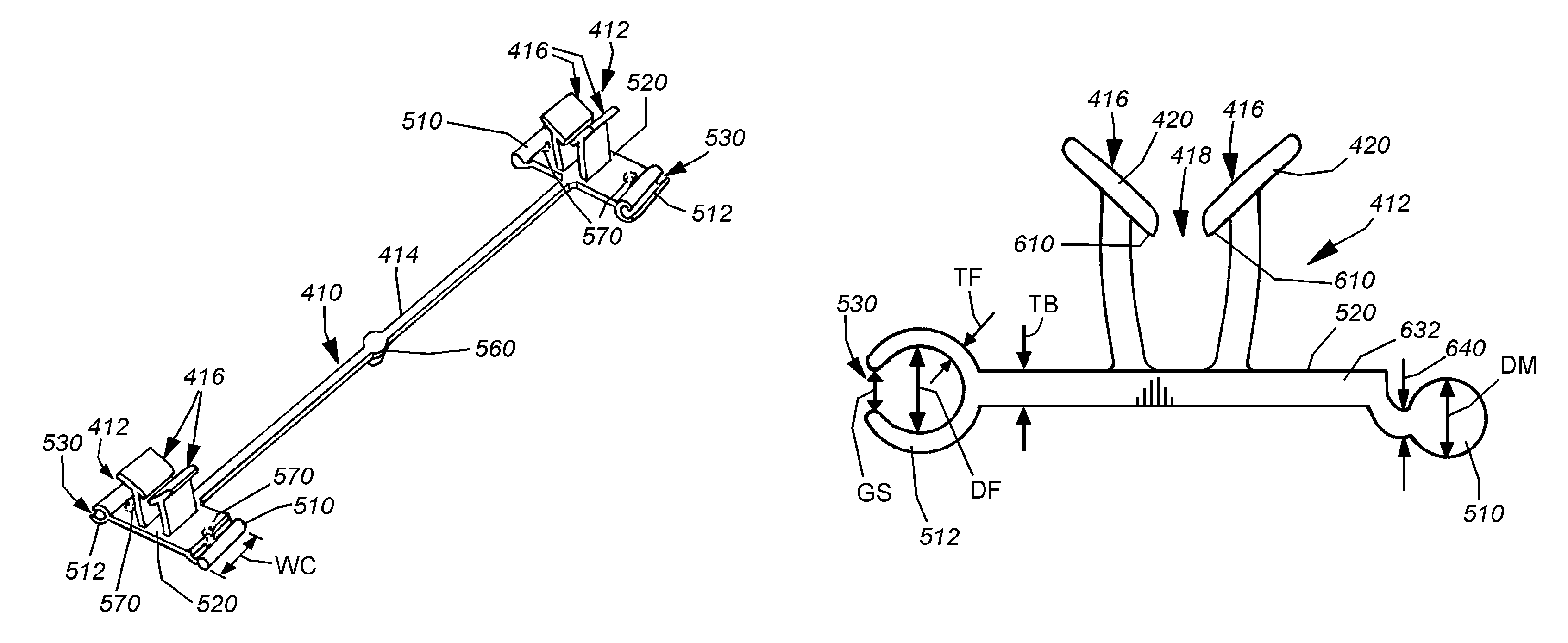
[0045]FIG. 4 shows a festooned grouping 400 of dual-ganged clips 410 according to an embodiment of this invention. This and other embodiments described with reference to FIGS. 1-18 embodiment detail a “higher-profile” clip, which can be readily substituted with the novel low-profile clip design described further below. With reference further to FIGS. 5 and 6, the clips 410 comprise a pair of opposed clip members 412 (also sometimes referred to herein as “clips”), joined by a central shaft segment 414. Each discrete clip 410 in the festooned grouping is a unitary structure, with the clip members 412 and adjoining intermediate segment 414 being molded together as a single unit. As will be described below alternate forming techniques, such as extrusion are also contemplated.

[0046]The clips 410 of this invention can be constructed from a variety of materials, which will also be described in further detail below. In general, the material should be durable, c...


PUM


Abstract

A low-profile clip adapted to secure a listing bead to a foam substrate and is constructed from a material that affords resilience, durability, high resistance to a wide range of temperatures during field use and seat assembly and ease of bead installation with high pull-out strength. The clip includes a base and a pair of legs extending upwardly from the base to a top barb. In this embodiment, the legs each extend upwardly from the base at a first angle of approximately 80 to 85 degrees and therefrom to each of the respective barbs at a second angle, with respect to a plane parallel to the base of approximately 88 to 90 degrees. In this manner the clip exhibits high performance while defining an overall height from tops of the legs to a bottom of the base of approximately ten millimeters or less making the clip particularly desirable for use in modern, thinner foam substrates.

Description

RELATED APPLICATIONS[0001]This application is related to U.S. patent application Ser. No. 11 / 737,362, entitled FESTOONED TRIM CLIP SYSTEM AND METHOD FOR ATTACHING FESTOONED CLIPS TO A SUBSTRATE, by Andrew W. Santin, et al., the teachings of which are expressly incorporated herein by reference.FIELD OF THE INVENTION[0002]This invention relates to trim and upholstery attachment mechanisms, and more particularly to clips for attaching trim and upholstery to foam and other resilient or flexible substrates.BACKGROUND OF THE INVENTION[0003]Modern fabric trim covers and their interconnected spring and cushion components (collectively termed “upholstery”), such as those used in vehicles, often carefully sculpted and shaped to produce a comfortable and aesthetically pleasing effect. As such, the fabric (typically cloth, vinyl or leather with an appropriate backing material) is secured at many locations along its surface to a resilient or flexible backing that defines the cushioned substrate ...

Claims


Application Information

Patent Timeline
Patent Type & Authority Patents(United States)
IPC IPC(8): A47C31/04
CPCA47C31/023B60N2/5825B60N2/6027Y10T428/24017Y10T24/44752Y10T24/45105Y10T24/309
Inventor SANTIN, ANDREW W.ROSSI, PASQUALEJONES, DAVID F.SCOTT, TIMOTHY E. T.
Owner HOPE GLOBAL DIV OF NFA
Why Eureka
Try Eureka