
Needle

a technology of needles and needles, applied in the field of needles, can solve the problems of affecting the accuracy of filling dosage containers, the control of the size and behaviour of liquid droplets, and the difficulty in obtaining plastic needles having the same strength characteristics

Active Publication Date: 2012-01-24
SANI TECH WEST INC
View PDF7 Cites 0 Cited by
  • Summary
  • Abstract
  • Description
  • Claims
  • Application Information

AI Technical Summary

Benefits of technology

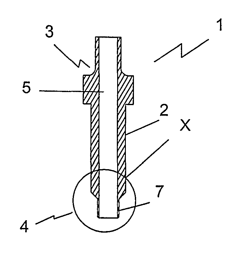
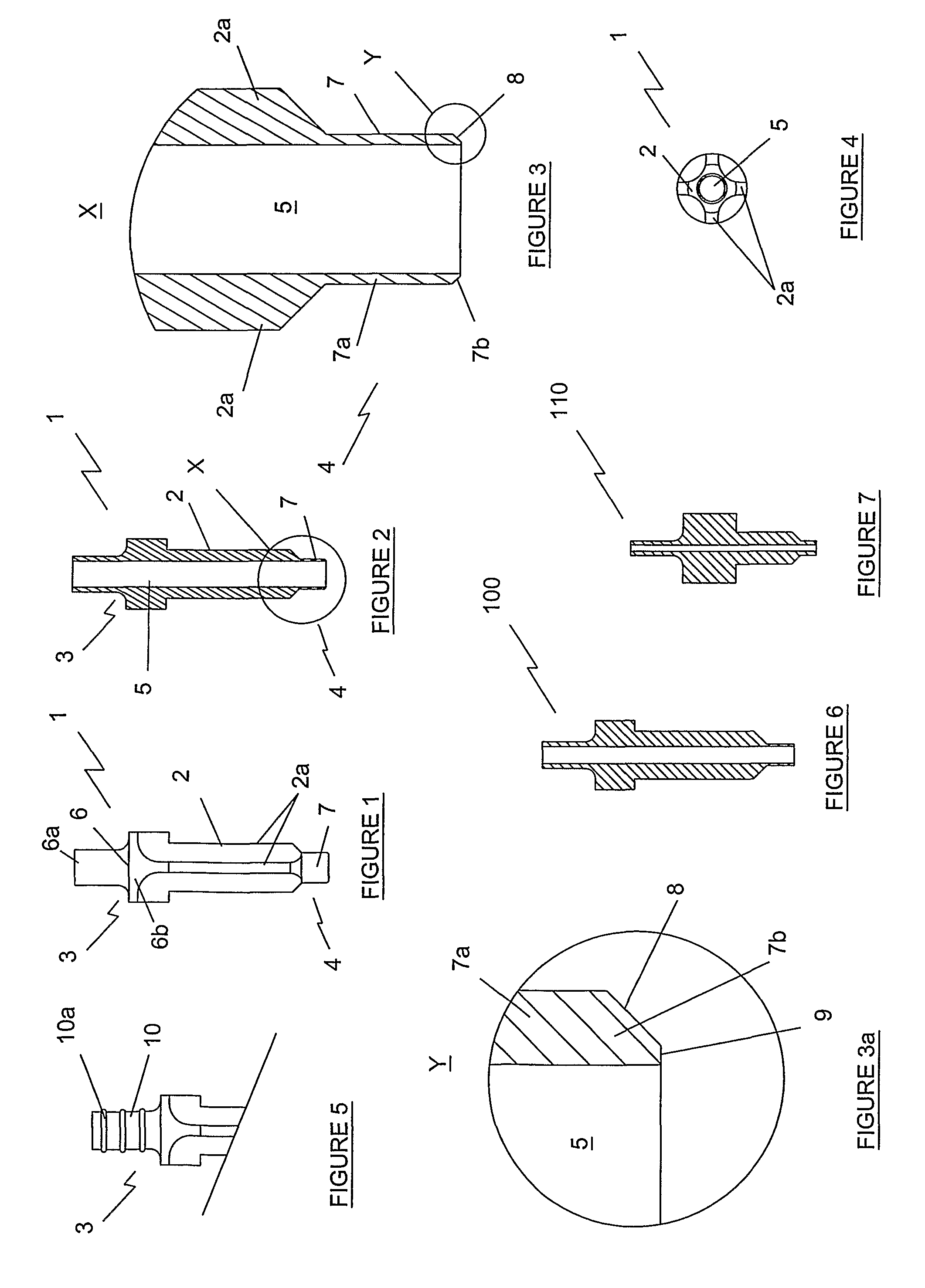
[0006]During a process of filling a dosage container using a filling needle, droplets of liquid may form at the needle tip when the liquid stream is shut off. It has been found that a needle having a tip with such a reduced wall-thickness about the channel opening enables the formation of smaller droplets in comparison with those formed at an opening of a needle having uniform wall thickness thereby increasing the accuracy of a fill. It has also been found that such smaller droplets are less likely to separate from the needle and affect the fill accuracy.
[0010]Ideally, the thickness of the wall material of the body of the needle is selected sufficient to provide the needle with the same strength and flexibility characteristics as those of a metal needle having substantially the same body length and substantially the same cross-sectional dimensions of the through passageway.

Problems solved by technology

The nature of plastics materials used for manufacture of disposable needles, and in particular, difficulty in obtaining plastic needles having the same strength characteristics as metal needles gives rise to problems such as control of size and behaviour of liquid droplets which may form at the needle tip at the time when the liquid stream is shut off.
This can affect the accuracy of filling dosage containers.

Method used


Image

  • Needle
  • Needle
  • Needle

Examples


Embodiment Construction

[0030]A filling needle according to the invention will now be described with reference to the drawings. The most preferred embodiments are illustrated in FIGS. 6 and 7.

[0031]Preferred materials for manufacture of the needle are polymeric materials suitable for manufacture of disposable needles, such as for example silicone or polyethylene. The most preferred materials are polyetherimide (PEI), polysulfone (PSU) and ethylene tetrafluoroethylene (ETFE). Plastics needles typically have thicker walls than similar needles made of metal so that the needle shaft will have strength and flexibility characteristics similar to a metal shaft.

[0032]Although the present invention is directed to overcoming problems associated with plastics needles, it will be appreciated that the needle of the invention is not limited to plastics materials, and other suitable materials may be used, for example metals, including stainless steel.

[0033]Referring to FIGS. 1 to 5, the needle 1 of a first embodiment com...


PUM


Abstract

A needle (1, 100, 110) for precision filling of dosage containers, such as vials, ampoules etc. is provided. The needle ideally comprises an elongate plastics body (2) having a through channel (5) extending between inlet (3) and outlet (4) openings. A tip portion (7b) at the outlet opening (4) has a chamfer (8) tapering towards the outlet opening (4) and an end surface (9) around the opening so that the tip portion (7b) is frusto-conical. The surface area of the end surface (9) is sufficiently smaller than the area of the cross-section of the needle body (2) so that in use the needle (1) is capable of providing for formation of smaller droplets of liquid at the outlet (4) compared to needles without such body thickness reduction at the time when the liquid flow through the needle is shut off. The end surface (9) may be so narrow as to take the form of a sharp rim.

Description

CROSS-REFERENCE TO RELATED APPLICATIONS[0001]This application is the National Stage of International Application No PCT / IE2006 / 000059, filed May 17, 2006, which claims the benefit of Irish Application No. IE S2005 / 0325, filed May 17, 2005, the contents of which is incorporated by reference herein.TECHNICAL FIELD[0002]The present invention relates to a needle and in particular to a needle for transfer of liquid to a receptacle such as a vial, ampoule, etc.BACKGROUND ART[0003]In the pharmaceutical industry it is known to use filling needles for precision transfer of liquids into dosage containers such as vials or ampoules or the like. During such transfer, liquid is supplied at a constant flow rate into the needle channel at one end of the needle and the liquid exits the channel at the other end of the needle. The liquid exits the needle in a continuous stream. In some applications disposable plastics needles are preferred in place of sterilisable metal needles. The nature of plastics...

Claims


Application Information

Patent Timeline
Patent Type & Authority Patents(United States)
IPC IPC(8): A61M5/00
CPCB01L3/0275B01L2300/0838
Inventor LIEPOLD, GERHARD
Owner SANI TECH WEST INC
Learn More