
Expander-integrated compressor and refrigeration-cycle apparatus with the same

a compressor and expansion mechanism technology, applied in the direction of lighting and heating apparatus, positive displacement liquid engines, liquid fuel engines, etc., can solve the problems of preventing an improvement in the efficiency of the refrigeration cycle apparatus, no longer being supplied to the partition member of the expansion mechanism, etc., to prevent heat transfer from the oil to the fluid in the expansion mechanism, stabilize the operation of the expander-integrated compressor, and maintain the reliability and efficiency of the expansion mechanism

Inactive Publication Date: 2012-01-31
PANASONIC CORP
View PDF12 Cites 2 Cited by
  • Summary
  • Abstract
  • Description
  • Claims
  • Application Information

AI Technical Summary

Benefits of technology

This configuration stabilizes the compression mechanism's operation, maintains efficient refrigeration performance, and prevents oil shortages, ensuring reliable lubrication and sealing while minimizing heat transfer to the expansion mechanism, thus enhancing the refrigeration cycle's efficiency and capacity.

Problems solved by technology

Therefore, when the oil level in the oil reservoir is lowered and becomes lower than the bottom end of the partition member, the oil no longer is supplied to the partition member of the expansion mechanism first.
Such heat transfer is preferably as low as possible since it causes an increase in enthalpy of the refrigerant that is discharged from the expansion mechanism and a decrease in enthalpy of the refrigerant that is discharged from the compression mechanism and thereby it prevents an improvement in the efficiency of the refrigeration cycle apparatus.

Method used


Image

  • Expander-integrated compressor and refrigeration-cycle apparatus with the same
  • Expander-integrated compressor and refrigeration-cycle apparatus with the same
  • Expander-integrated compressor and refrigeration-cycle apparatus with the same

Examples


first embodiment

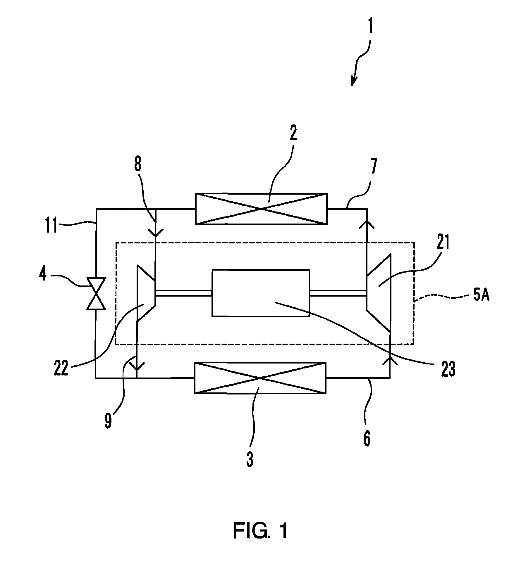
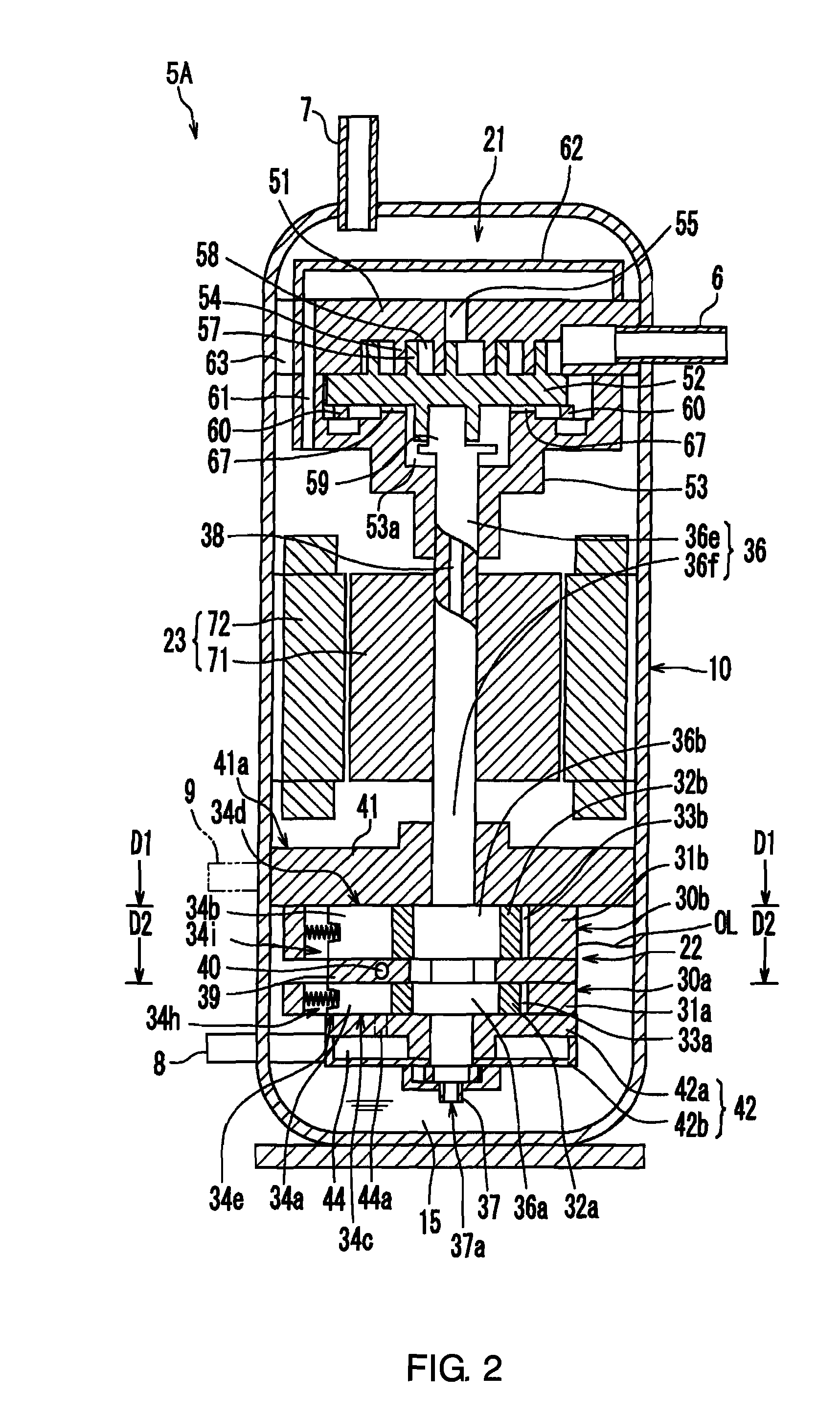
[0098]As shown in FIG. 1, an expander-integrated compressor 5A according to this embodiment is incorporated in a refrigerant circuit 1 of a refrigeration cycle apparatus. The expander-integrated compressor 5A includes a compression mechanism 21 for compressing the refrigerant and an expansion mechanism 22 for expanding the refrigerant. The compression mechanism 21 is connected to an evaporator 3 through an intake pipe 6 and also is connected to a radiator 2 through a discharge pipe 7. The expansion mechanism 22 is connected to the radiator 2 through an intake pipe 8 and also is connected to the evaporator 3 through a discharge pipe 9. Reference numeral 4 indicates an expansion valve provided for a subcircuit 11, and reference numeral 23 a motor to be described later.

[0099]This refrigerant circuit 1 is filled with a refrigerant such that it reaches a supercritical state in the high-pressure portion (i.e. the portion extending from the compression mechanism 21 to the expansion mechani...

second embodiment

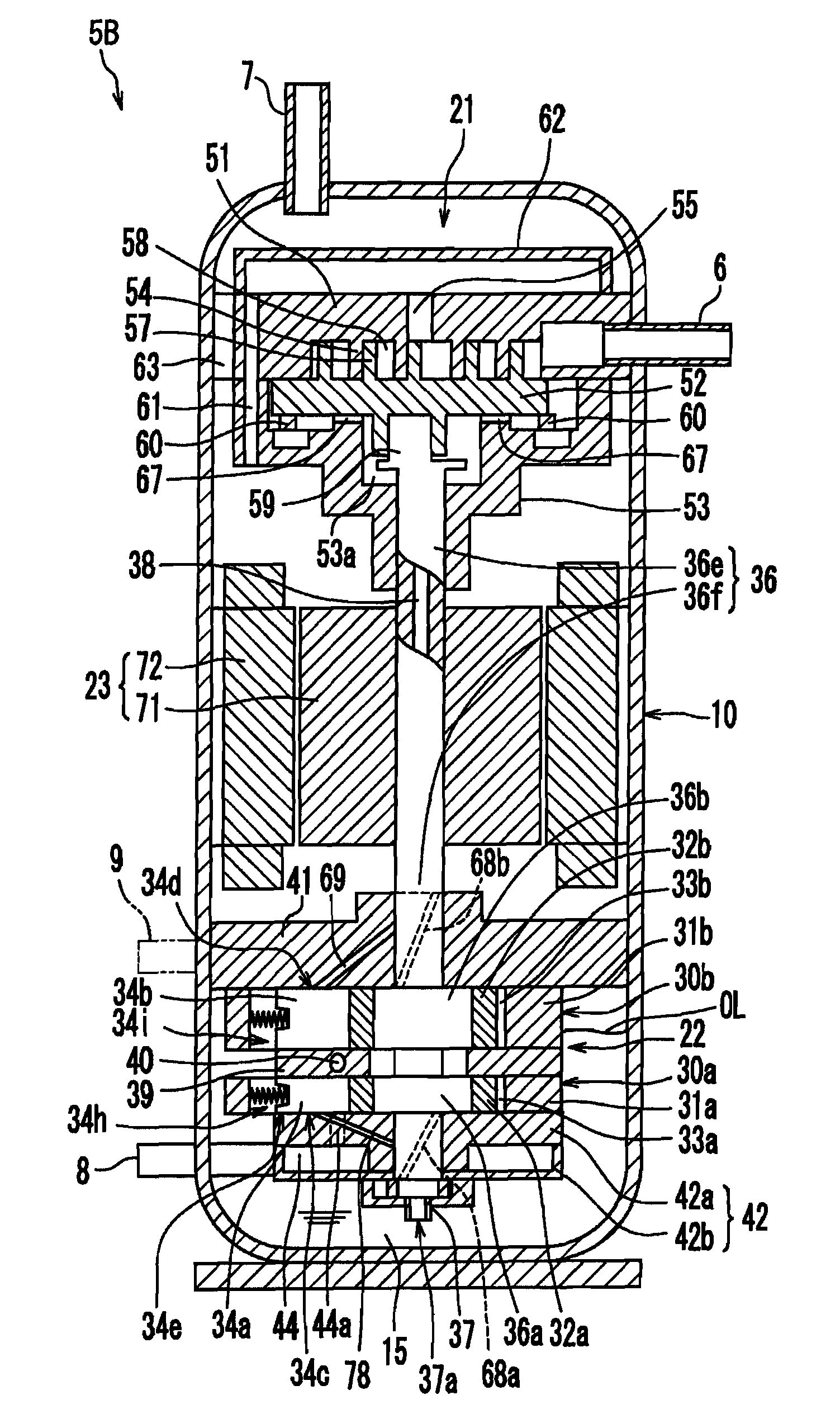
[0137]In the first embodiment, a part or the whole of the expansion mechanism 22 is immersed in the oil contained in the oil reservoir 15, and the oil is supplied from the oil reservoir 15 directly to the vanes 34a and 34b. An expander-integrated compressor 5B according to this embodiment not only supplies the oil directly from the oil reservoir 15 but also supplies the oil reliably to the vanes 34a and 34b through provision of an oil supply passage for supplying the oil to the vanes 34a and 34b from the rotating shaft 36 side even when the oil level OL has been lowered.

[0138]As shown in FIG. 4, the expander-integrated compressor 5B according to this embodiment has substantially the same configuration as that of the expander-integrated compressor 5A according to the first embodiment. Therefore, only the parts that are different will be described.

[0139]An axially and spirally extending oil supply groove 68a is formed in the inner circumferential surface of the lower bearing 42 of the...

third embodiment

[0144]As shown in FIG. 5, an expander-integrated compressor 5C according to this embodiment also has substantially the same configuration as that of the expander-integrated compressor 5A according to the first embodiment. Therefore, only the parts that are different will be described.

[0145]This expander-integrated compressor 5C is provided with the oil supply grooves 68a and 68b as in the second embodiment. In addition, an upper through hole 66 that penetrates through the upper bearing 41 from its upper face 41a to its bottom face is provided in a portion of the upper bearing 41 located on the rear chamber 34i. Furthermore, the cross-sectional shape of the partition plate 39 is formed to be the same as (to coincide with) that of cylinders 31a and 31b, and a communication hole 64 that allows the rear chamber 34h and the rear chamber 34i to communicate with each other is formed in the partition plate 39.

[0146]With such a configuration, similarly in this expander-integrated compressor ...


PUM


Abstract

An expander-integrated compressor (5A) has a compression mechanism (21) for compressing a refrigerant and an expansion mechanism (22) for expanding the refrigerant. The compression mechanism (21) is located above the expansion mechanism (22) inside a closed casing (10) and shares a rotating shaft (36) with the expansion mechanism (22). An oil pump (37) is provided at the lower end of the rotating shaft (36). The oil pump (37) is immersed in oil in an oil reservoir (15). Usually, the oil is placed in the oil reservoir (15) in such a manner that the oil level (OL) is located above a lower end portion (34e) of a vane (34a) of a first expansion section (30a). More preferably, the oil is placed in such a manner that the expansion mechanism (22) is immersed in the oil. An oil supply passage (38) for guiding the oil to the compression mechanism (21) is formed inside the rotating shaft (36). A suction port (37a) of the oil pump (37) is provided below the lower end portion (34e) of the vane (34a).

Description

TECHNICAL FIELD[0001]The present invention relates to expander-integrated compressors, each of which includes a compression mechanism for compressing a fluid and an expansion mechanism for expanding the fluid, and refrigeration cycle apparatuses with the same.BACKGROUND ART[0002]Conventionally, an expander-integrated compressor has been known in which a compression mechanism and an expansion mechanism are disposed vertically within a closed casing (see, for example, WO 2005 / 088078and JP 2003-139059 A).[0003]The expander-integrated compressor disclosed in FIG. 2 of WO 2005 / 088078 includes a casing formed of a closed casing as well as an expansion mechanism, a motor, and a compression mechanism that are disposed inside the casing. The expansion mechanism, motor, and compression mechanism are disposed sequentially from the upper part toward the lower part. A rotating shaft of the compression mechanism extends upwards, and the expansion mechanism is coupled to this rotating shaft. That ...

Claims


Application Information

Patent Timeline
Patent Type & Authority Patents(United States)
IPC IPC(8): F25B43/02F01C21/04F01C21/06F01C1/02
CPCF04B39/02F04C23/003F04C23/008F04C29/023F04C29/025F01C13/04F04C23/02F04C2240/603F04C2240/809
Inventor HASEGAWA, HIROSHIOGATA, TAKESHIMATSUI, MASARUOKAICHI, ATSUOWADA, MASANOBUTAKAHASHI, YASUFUMI
Owner PANASONIC CORP
Learn More