Reusable infusion bag

a vacuum bag and infusion bag technology, applied in the field of aircraft components, can solve the problems of unintentional movement or shift, time-consuming and error-prone, and the need to individually cut the flow media, breather cloth, and vacuum bag,

Active Publication Date: 2012-01-31
SPIRIT AEROSYSTEMS
View PDF40 Cites 18 Cited by
  • Summary
  • Abstract
  • Description
  • Claims
  • Application Information

AI Technical Summary

Problems solved by technology

Some disadvantages to the VARTM method include the need to individually cut the flow media, breather cloth, and vacuum bag for placement over the composite material, particularly when manufacturing complex-shaped composite parts.
This may be time consuming and error-prone.
And, because the flow media, breather cloth, and vacuum bag are separate parts laid together, they may unintentionally move or shift during the vacuum and curing process.
Another disadvantage to the traditional VARTM method is that the vacuum bag, flow media, and breather cloth are not reusable.
Finally, in the traditional VARTM process, once the vacuum pump is removed, the vacuum bag tape often leaks or bleeds off vacuum, and the vacuum bag therefore loses vacuum integrity when the vacuum source is turned off or disconnected.
This, in turn, may negatively impact the structural integrity of the resulting part.

Method used


Image

  • Reusable infusion bag
  • Reusable infusion bag
  • Reusable infusion bag

Examples


Embodiment Construction

[0021]The following detailed description of the invention references the accompanying drawings that illustrate specific embodiments in which the invention can be practiced. The embodiments are intended to describe aspects of the invention in sufficient detail to enable those skilled in the art to practice the invention. Other embodiments can be utilized and changes can be made without departing from the scope of the present invention. The following detailed description is, therefore, not to be taken in a limiting sense. The scope of the present invention is defined only by the appended claims, along with the full scope of equivalents to which such claims are entitled.

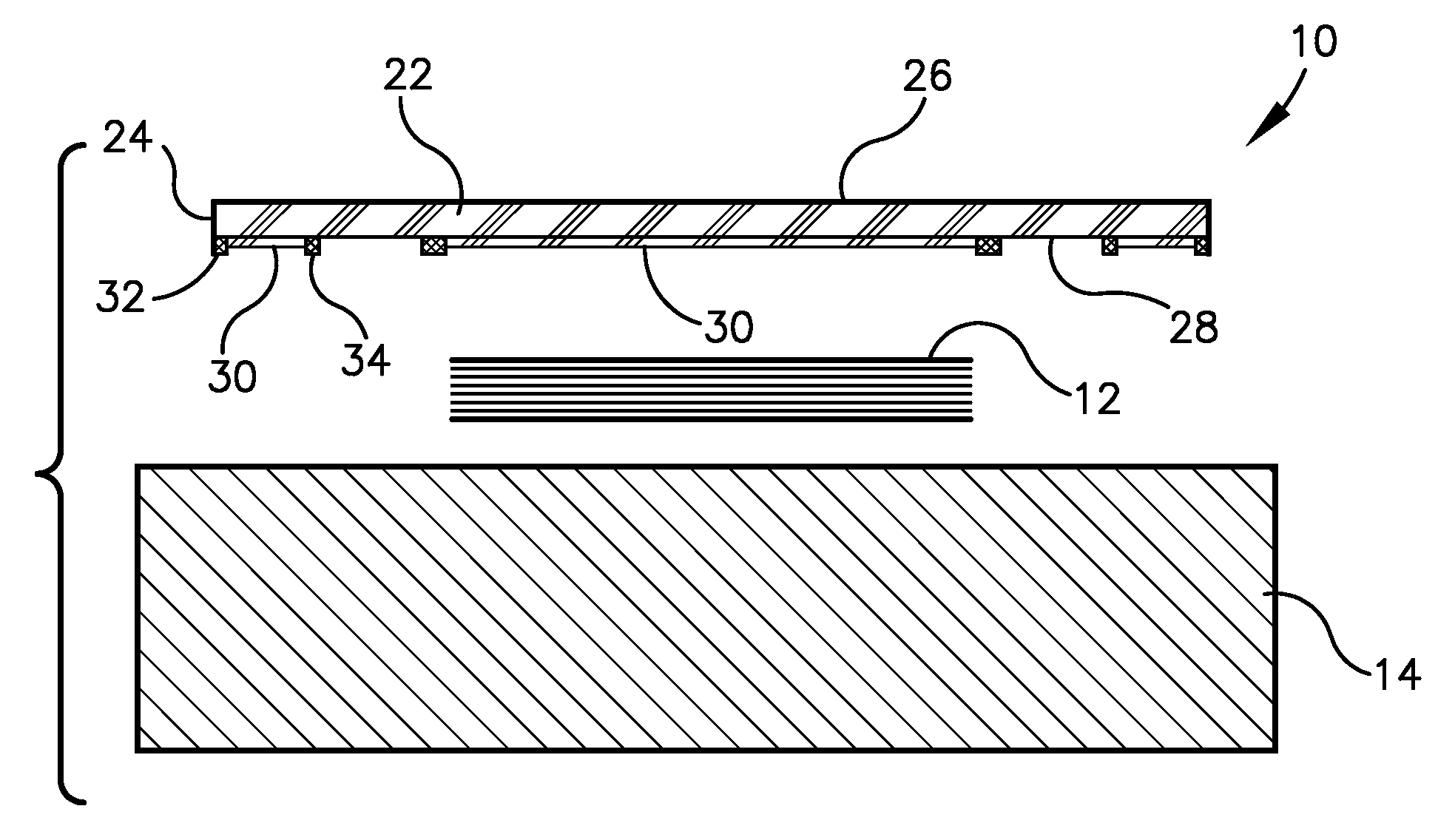
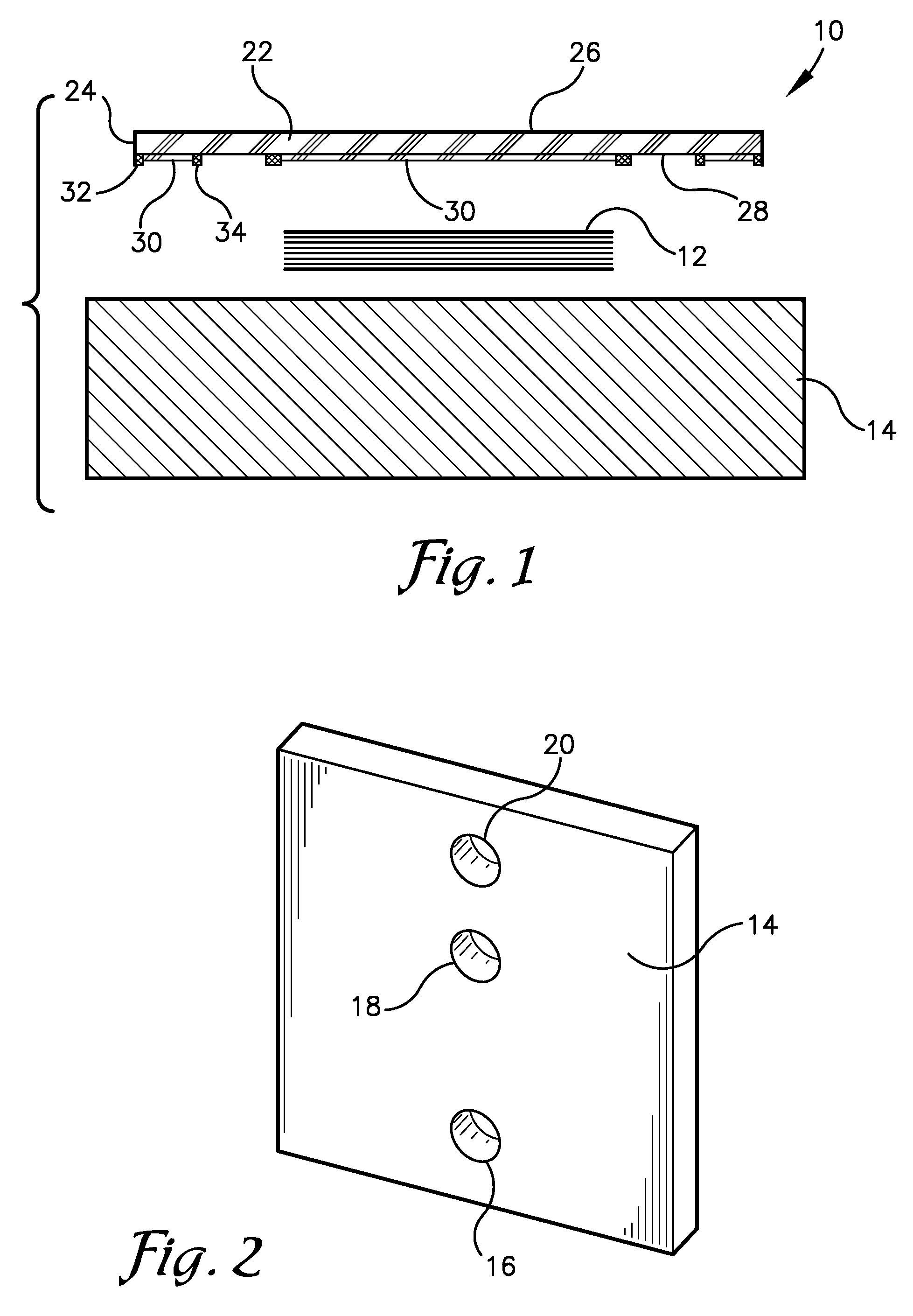
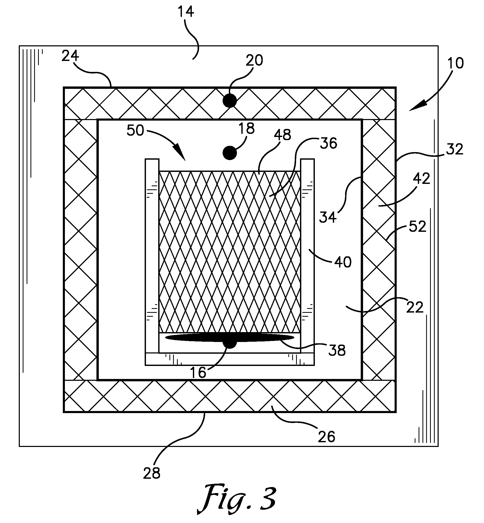
[0022]As illustrated in FIGS. 1-4, embodiments of the present invention provide a reusable apparatus 10 and method 200 for forming a composite part through vacuum assisted resin transfer molding (VARTM). The reusable apparatus 10 may be configured to vacuum seal a curable material 12 against a tool 14 and disperse a per...


PUM

PropertyMeasurementUnit
widthaaaaaaaaaa
areaaaaaaaaaaa
vacuumaaaaaaaaaa

Abstract

A reusable apparatus and method for forming a composite part through vacuum assisted resin transfer molding (VARTM). The reusable apparatus may be configured to vacuum seal a curable material, such as composite material, against a tool and disperse a permeating substance such as liquid resin through the curable material. The reusable apparatus may comprise a sheet of material such as rubber having a plurality of surface deviations facing the curable material and the tool. The surface deviations may provide paths for evenly distributed air flow as air is evacuated from between the sheet of material and the tool. Additionally, the surface deviations may allow the permeating substance to be evenly dispersed throughout the curable material. A vacuum outlet of the tool may be positioned between two sealing apparatuses to provide continuous vacuum suction proximate a perimeter of the sheet of material to prevent air from leaking in.

Description

BACKGROUND[0001]1. Field[0002]The present invention relates to aircraft components. More particularly, the present invention relates to vacuum assisted resin transfer molding with a reusable vacuum bag.[0003]2. Related Art[0004]Vacuum assisted resin transfer molding (VARTM) is a composite manufacturing process in which dry fibers of composite material are laid on a tool beneath a nylon vacuum bag and vacuum sealed while liquid resin is drawn through the composite material with a vacuum pump. Traditionally, a flow media or resin distribution media made of a nylon, plastic, or metal and having a high permeability is placed over the composite material to allow resin to flow over it and subsequently be evenly dispersed throughout the composite material. Additionally, a breather cloth made of fiberglass or peel-ply may be placed beneath the nylon vacuum bag to help pull resin through the material and allow air to be evacuated from between the nylon vacuum bag and the tool. The nylon vacu...

Claims


Application Information

Patent Timeline
Patent Type & Authority Patents(United States)
IPC IPC(8): B29C70/44B29C70/48
CPCB29C70/443B29C70/548Y02T50/433Y02T50/40
Inventor ROSS, WILLIAM TODBUXMAN, JEFFERY MAX
Owner SPIRIT AEROSYSTEMS
Why Eureka
Try Eureka