Vacuum acoustic ceiling removal system

a vacuum acoustic ceiling and scraper technology, applied in the field of vacuum acoustic ceiling scraper system, can solve the problems of messy and potentially hazardous removal, laborious, and even more potentially stringent removal attempts on a dry basis

Inactive Publication Date: 2012-02-07
VIVIANO JAMES C
View PDF17 Cites 19 Cited by
  • Summary
  • Abstract
  • Description
  • Claims
  • Application Information

AI Technical Summary

Benefits of technology

[0024]A ceiling scraper unit attached to an elongated handle allows a user to reach aloft and scrape acoustic “popcorn” ceiling material from an acoustic ceiling, and contain same via a tray-shaped trough, or hopper, which is connected at the forward end of said handle. The hopper has a scraper blade across a top front upper leading edge. The tray-shaped trough includes a vacuum opening in a lower rearward portion for a vacuum suction to be applied to the interior of said hopper for removal of debris scraped from a ceiling by said blade. The tool's handle includes a cantilever arm rest attachment at the lowest end of the elongated handle which allows a user to apply a two arm ceiling scraping force at said blade location.
[0025]The unit includes a concave upper surface at the handle end nearest the user which concave surface is shaped to conform to an underarm area; and located just forward of that concave area, the handle includes a pistol-like grip and a double bend upward offset in the handle. A transparent shroud covers the base of said collector, which transparency allows the user to see and guide the scraper blade during a ceiling scraping maneuver. Proper scraping of a ceiling has a range of preferred angles of attack by the flexible blade and said unit further includes adjustability features for the flexible blade per se and / or for the tray itself. Additionally, skid plates connected to the tray allows the user to apply proper—yet adjustable—angle positioning against the ceiling in a simple efficient manner.OBJECTS OF THE INVENTION
[0026]It is an object of this invention to allow a ceiling treatment operation by a user standing on the floor below in a simple and efficient manner.
[0027]It is still a further object of this invention to provide a double bend cantilever handle of sufficient length and novel shape so as to provide lift and scraping and / or other two arm treating forces to be applied to an overhead ceiling by a new and improved ceiling tool.

Problems solved by technology

Acoustic ceiling removal is a messy and potentially hazardous endeavor.
It is labor intensive, mostly involving a trowel-like scraper, broom, plastic drop cloths, ladder, sand paper and dust pan and vacuuming equipment.
Removal attempts on a dry basis are even a more potentially stringent problem because of the dust, dirt and debris that is created in the air.
Breathing such a foul dust, dirt and debris mixture is not healthy, to say the least.
Moreover, this manual prior art approach is also time consuming, very costly and creates health hazards as mentioned above.
Unless one wears some form of a mask and breathing apparatus, there is very little protection from the dust and dirt mixture in the air.
In short summary, acoustic ceiling removal is a drawn out, dangerous and costly affair.

Method used


Image

  • Vacuum acoustic ceiling removal system
  • Vacuum acoustic ceiling removal system
  • Vacuum acoustic ceiling removal system

Examples


Embodiment Construction

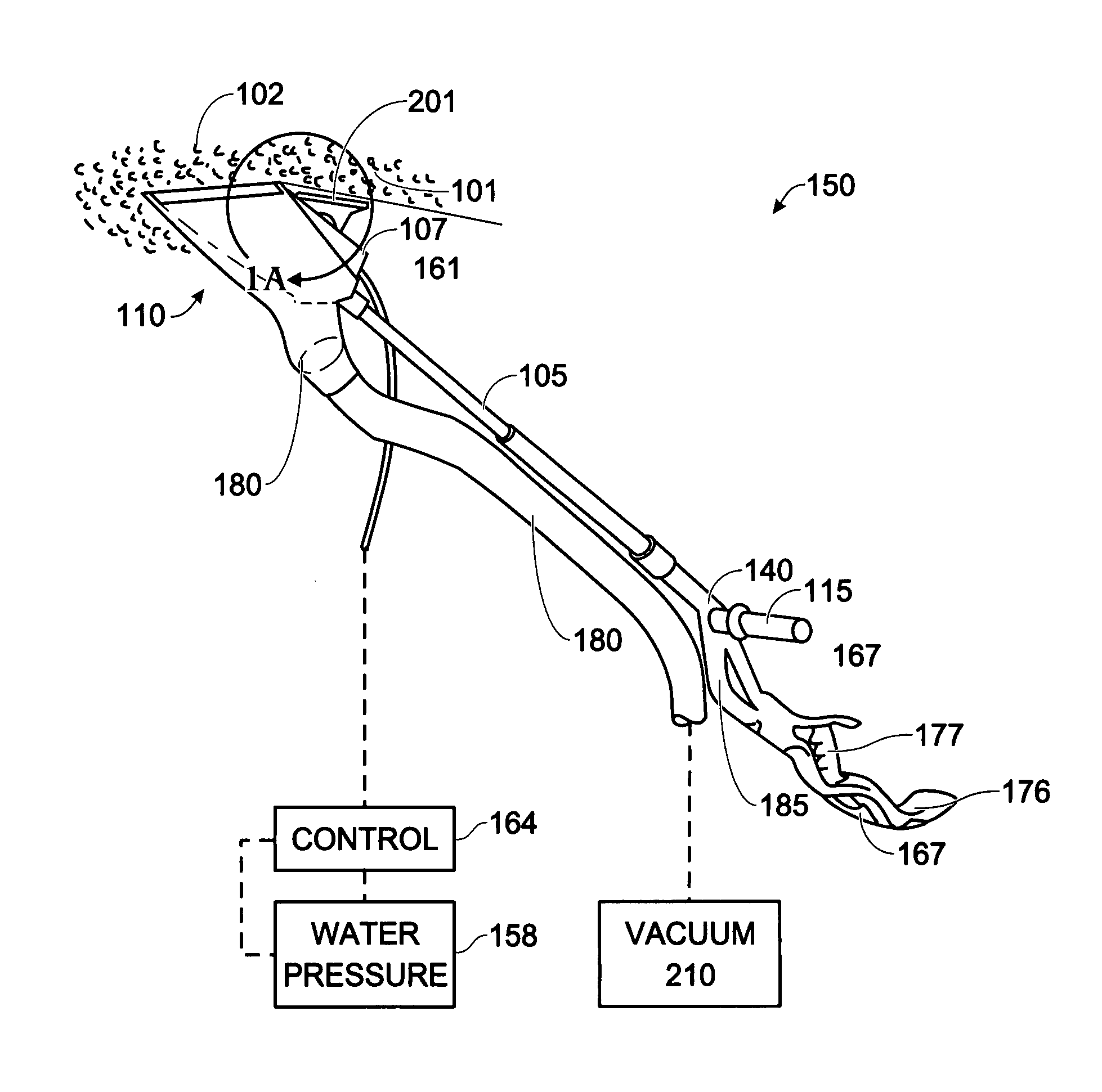
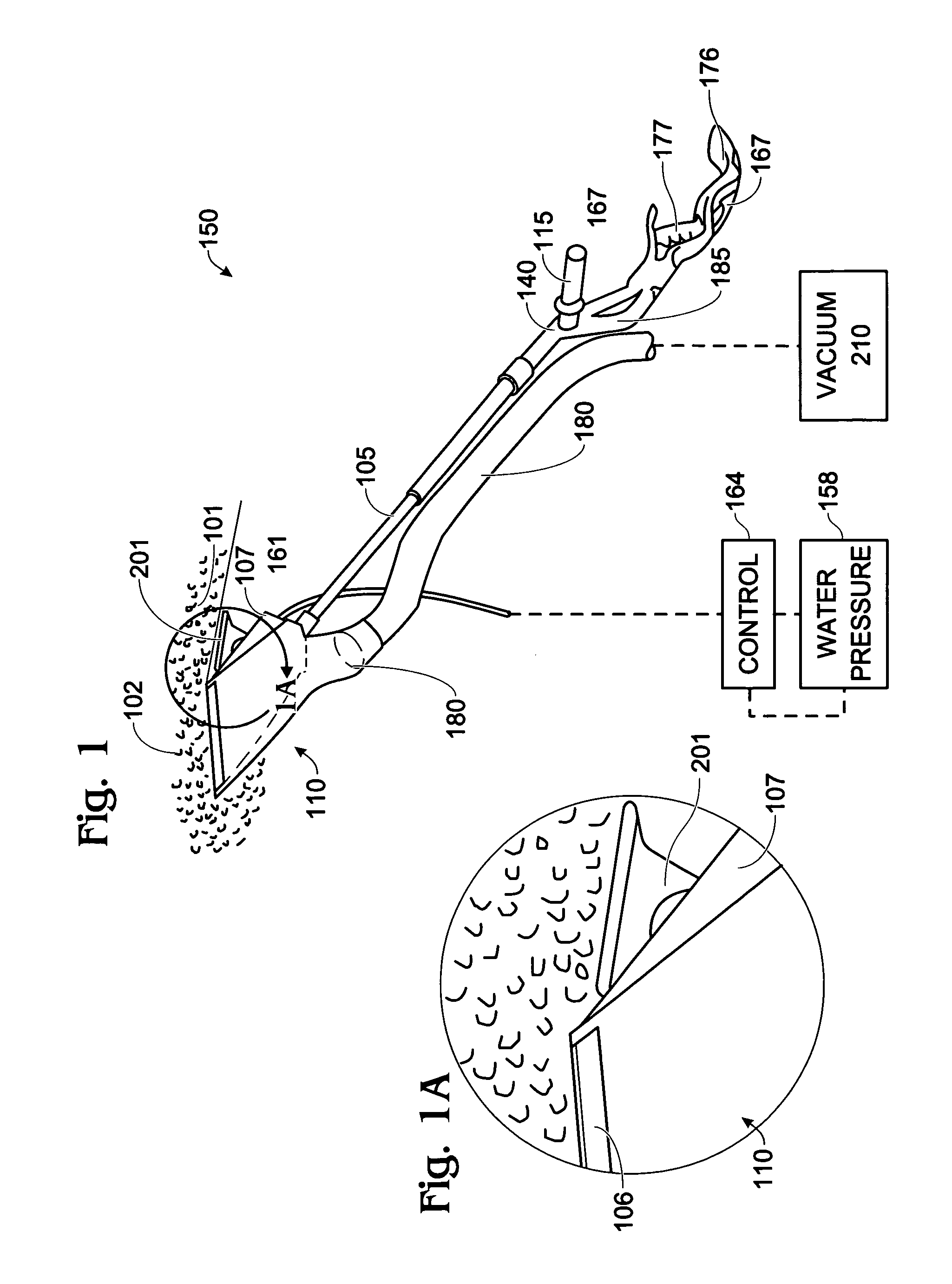
[0029]In FIGS. 1 and 5 a scraper blade hopper assembly 110 is built into—or fastened onto handle 140—including the forwardly-located telescope arm 105—which arm extends from a side extension handle 115 and an arm support area 175. A key feature of this invention resides in the overall design of handle 140 that is cantilever supported by the user in order to scrape acoustic material from a ceiling 102 being treated. FIG. 5A depicts—at a slightly different angle—an enlarged area of the end of handle 150 that is nearest the user. The cantilever nature of the handle is described in more detail hereinafter.

[0030]Handle 140 at it rearward end includes a cantilever arm support area 175 with rocker tip 176 a strut 167 and an ergonomic hand grip 177. The upward rocker curvature of the cantilever support 176 and the forward leaning pistol-like hand grip 177 and forward strut 167 together provide a ready-made upward force to hold handle 140 aloft during a ceiling treatment procedure with my VA...


PUM


Abstract

A ceiling tool assembly has a unique ergonomically curved handle supported by a user at its rearward end with a cantilever rocker-shaped arm and forwardly slanted pistol grip. A curved concave surface conforms to the underarm part of a user's forearm above the elbow and further includes a forwardly slanted pistol grip with stub extension and an upward handle offset bend. Scraping force is provided by handle shape and handle attachments of my scraping unit for easy removal of popcorn from an overhead ceiling. A forearm resting area allows the user to provide either a right handed or left handed lifting force to the scraper unit. The offset portion, provided at the mid point of the handle, together with a handle attachment / design allows a two arm back and forward scraping force to be exerted along the length of the scraper unit.

Description

BACKGROUND OF THE INVENTION[0001]This is a regular patent application that is being timely filed within the time period allotted from a Provisional Application Entitled Vacuum Acoustic Ceiling Removal System as filed on Jul. 10, 2007 having the same inventor as hereof and awarded Ser. No. 60 / 959,112. VACRS™ stands for Vacuum Acoustic Ceiling Removal System. As noted in the provisional application, this is an adopted Trademark designated for the blade and hopper portion of the system. The handle, being capable of supporting more than one ceiling treatment tool, has been named a Hi Pro Tool as an adopted trademark soon to be seen on Applicant's hiprotool.com web site.FIELD OF THE INVENTION[0002]This invention relates to a ceiling treatment tool that is primarily useful for modernizing your home / office. Both a tool apparatus and a method of tool use for removing “popcorn” or “cottage cheese” from ceilings are presented. More specifically, the field of this invention relates to a vacuum...

Claims


Application Information

Patent Timeline
Patent Type & Authority Patents(United States)
IPC IPC(8): A47L5/00A47L9/06A47L13/02A47L17/06A47L23/22B25G1/10
CPCB25G1/102Y10T16/476
Inventor VIVIANO, JAMES C.
Owner VIVIANO JAMES C
Why Eureka
Try Eureka