
Auxiliary rotary tool drive for hand-held power tools

a technology of auxiliary rotary tool and power tool, which is applied in the direction of portable power-driven tools, drilling machines, manufacturing tools, etc., can solve the problems of increasing the probability of dropping and losing a bit or other rotary tool, and affecting the safety of the operation

Active Publication Date: 2012-02-07
HAYS JOHN N
View PDF17 Cites 14 Cited by
  • Summary
  • Abstract
  • Description
  • Claims
  • Application Information

AI Technical Summary

Benefits of technology

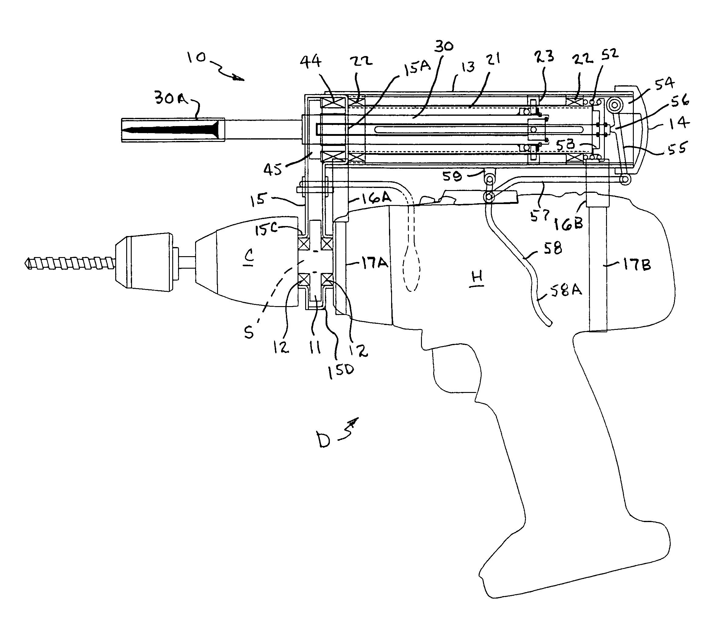
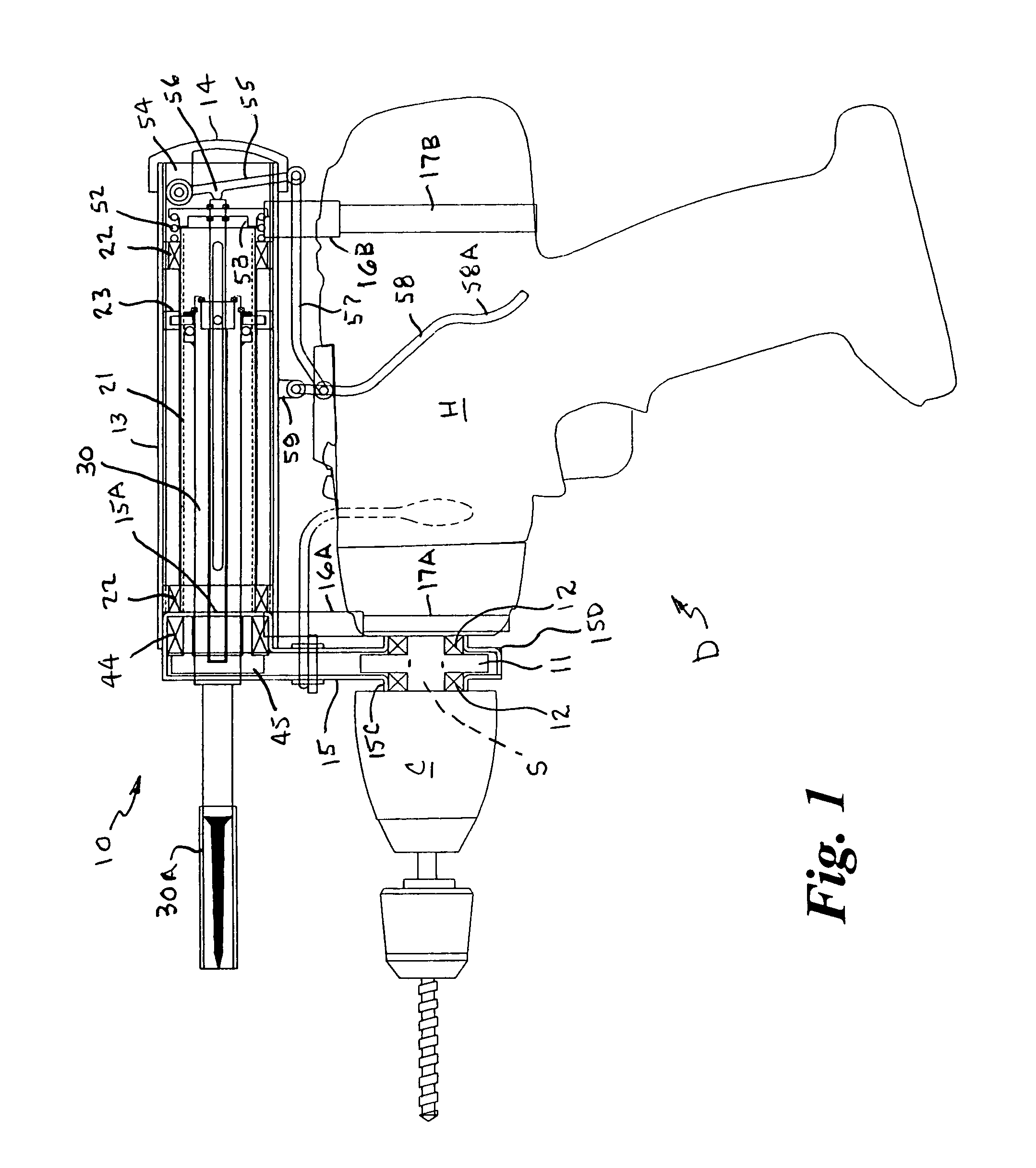
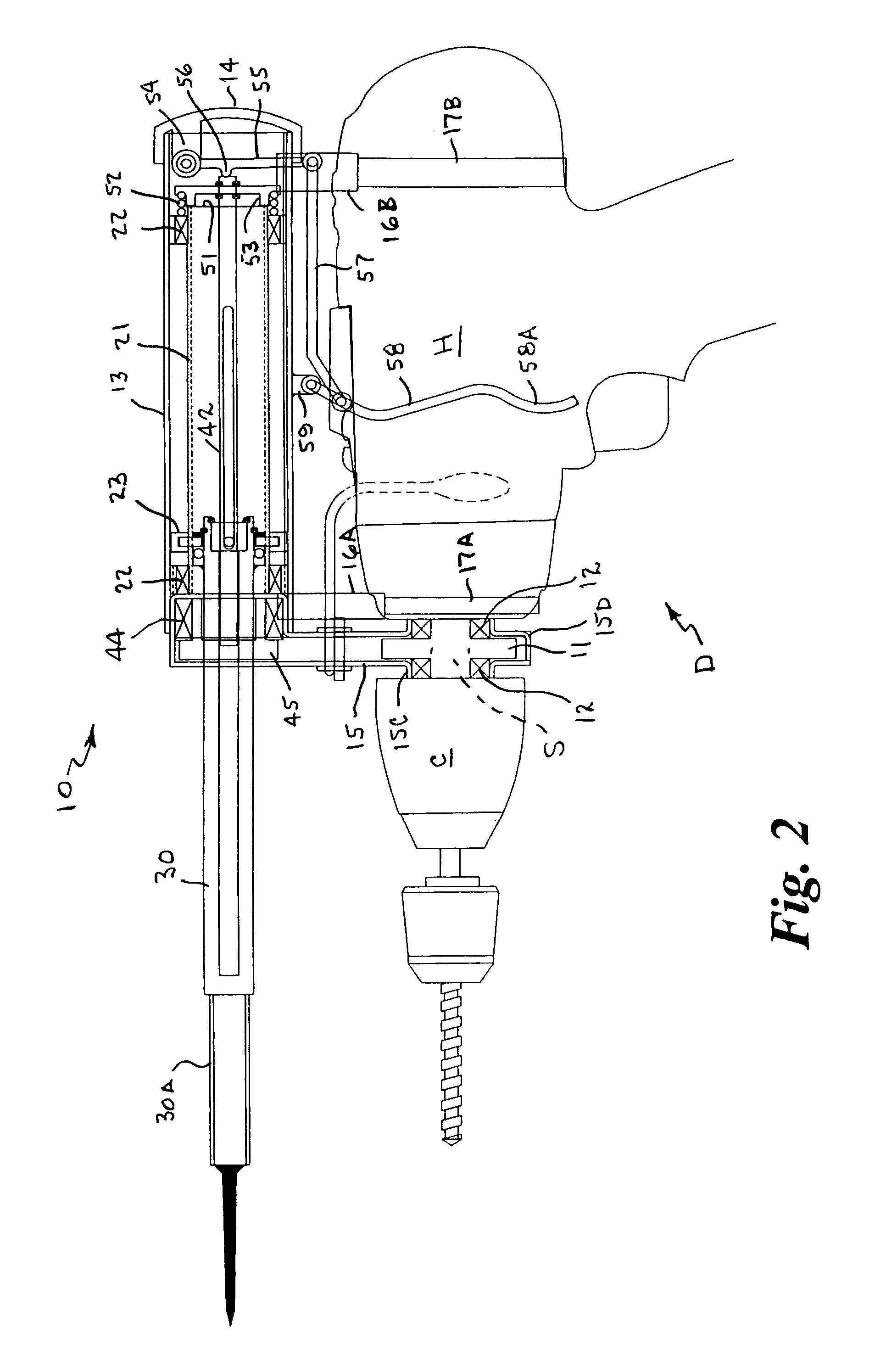
[0024]The present invention overcomes the aforementioned problems and is distinguished over the prior art by an auxiliary rotary tool drive apparatus mounted on, or an integral component of, and driven by, a conventional hand-held rotary power tool, such a rotary drill, which has an extendable and retractable auxiliary drive shaft and gear assembly operable using only the hand grasping the drill for driving screws, fasteners, bits or other work performing member attached to the auxiliary drive shaft, without having to move or remove the existing drill bit or work performing member from the chuck of the power tool. The auxiliary drive shaft is driven by a primary drive gear installed on the drive shaft and connected with the gear assembly drive train of the drill and operated using only the hand grasping the power tool by pressing a lever in combination with the trigger and forward / reverse control on the power tool.
[0025]One of the features and advantages of the present auxiliary rotary tool drive apparatus is that it provides users forced to wear heavy gloves or users having the use of only one hand, with the utility / ability to complete the tasks of predrilling a pilot hole and driving a screw or other fastener into the hole using a single hand without pause or re-grasping between the two tasks.
[0026]Another feature and advantage of the present auxiliary rotary tool drive apparatus is that it provides users that have artificially restricted dexterity, such as astronauts, deep sea divers, arctic technicians, or anyone that must drill holes and drive fasteners in an environment of restricted dexterity or movement, with the utility / ability complete the tasks of predrilling a hole and driving a screw, fastener into the hole using a single hand without pause or re-grasping between the two tasks.

Problems solved by technology

Both of these scenarios are time consuming and changing bits greatly increases the probability of dropping and losing a bit or other rotary tool.
Since these procedures require both hands to change the bit, the user is precluded from grasping a secure structure while completing the bit changing process, which can be potentially dangerous if done on a ladder, scaffold, or any high or unstable platform.
This process of changing back and forth between the required drills is time consuming and quickly becomes tedious, particular when it is done frequently or repetitively.
However, none appear to have successfully solved all the problems, nor appear to be capable of drilling a pilot hole and driving a screw immediately in the hole using only one hand and without turning or regrasping the drill or tool.
There are several patents directed toward various rotary tools with more than one output; however, they all share similar drawbacks when faced with the task of drilling a hole and subsequently driving a screw in the hole.
The disadvantage of this tool is that the toolheads extend therefrom in the same direction and operate at roughly the same working length.
The tool is not able to drill a hole and subsequently drive a screw in the hole without first reversing shaft rotation and releasing, turning and regrasping the tool, which is a cumbersome and time-consuming process.
In addition, the perpendicular drives could result in interference when working in a corner.
These factors would make applying this invention to drilling and rotary fastening very impractical and inconvenient.
This results in a cumbersome and time-consuming process.
The drawback to this method is that it is cumbersome to use and requires two hands to operate and change the selected rotary tool.
As previously mentioned, the drawback to these inventions is that they are all cumbersome to operate and require two hands to operate and change the selected rotary tool.

Method used


Image

  • Auxiliary rotary tool drive for hand-held power tools
  • Auxiliary rotary tool drive for hand-held power tools
  • Auxiliary rotary tool drive for hand-held power tools

Examples


Embodiment Construction

[0050]Detailed descriptions of the preferred embodiments are provided herein. It is to be understood, however, that the present invention may be embodied in various forms. Therefore, specific details disclosed herein are not to be interpreted as limiting, but rather as a basis for the claims and as a representative basis for teaching one skilled in the art to employ the present invention in virtually any appropriately detailed system, structure or manner.

[0051]The hand-held rotary power tool depicted in the drawing figures is shown and described, for purposes of example only, as a conventional hand-held power drill, and it should be understood that the rotary power tool may be of any conventional type that has a housing containing a drive train connected with a power transmitting shaft (drive shaft, spindle or anvil) that extends forwardly from the housing and has a chuck or holding member mounted at the outer end thereof. For ease of understanding and simplifying the detailed descr...


PUM

PropertyMeasurementUnit
Lengthaaaaaaaaaa
Pressureaaaaaaaaaa
Diameteraaaaaaaaaa

Abstract

An auxiliary rotary tool drive apparatus mounted on, or an integral component of, hand-held rotary power tool has an extendable and retractable auxiliary drive shaft and a gear assembly that is selectively operatively engaged with the power transmitting shaft and gear assembly of the power tool and driven thereby using only the hand grasping the power tool for driving screws, fasteners, bits or other work performing members attached to the auxiliary drive shaft without having to move or remove the existing work performing member from the holding member of the power tool.

Description

CROSS REFERENCE TO RELATED APPLICATION[0001]This application claims priority of U.S. Provisional Application Ser. No. 61 / 124,317, filed Apr. 17, 2008.BACKGROUND OF THE INVENTION[0002]1. Field of the Invention[0003]This invention relates generally to hand-held power tools, and more particularly, to an auxiliary rotary tool drive apparatus that is mounted on, or an integral component of, a hand-held rotary power tool, such a rotary drill, and has an extendable and retractable auxiliary drive shaft and a gear assembly that is selectively operatively engaged with the drive shaft and gear assembly of the power tool and driven thereby using only the hand grasping the drill for driving screws, fasteners, bits or other work performing members attached to the auxiliary drive shaft without having to move or remove the existing drill bit or work performing member from the chuck of the power drill.[0004]2. Background Art[0005]As used herein, the term “rotary power tool” means a tool having a ho...

Claims


Application Information

Patent Timeline
IPC IPC(8): B25F3/00
CPCB25F3/00
Inventor HAYS, JOHN N.
Owner HAYS JOHN N
Learn More